AMP1-DA
User Manual P/N
821530
Rev-
C
© 2006 Wohler Technologies Inc. ALL rights reserved
13
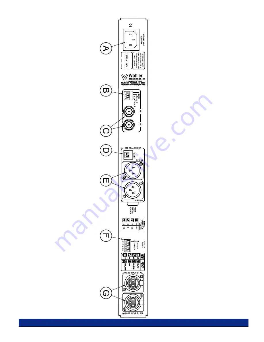
Section 2: Operation
Figure-2b: Rear Panel Features
Page 1: ...odulePCBCircuitDescription GeneralLevelMeterPCBDescriptions SeriesIILevelMeterRearPanelDIPSettings SeriesIILevelMeterInternalDIPSettings SeriesIILevelMeterInternalDIPLocations Mute on Error Header H12...
Page 2: ...ing walked on or pinched particularly at plugs convenience receptacles and the point where they exit from the apparatus 11 Only use attachments accessories specified by the manufacturer 12 Use only wi...
Page 3: ...1 DA User Manual P N 821530 Rev C 2006 Wohler Technologies Inc ALL rights reserved 3 General Features and Specifications Description Features Applications Specifications Other Options Section 1 12 01...
Page 4: ...the selected stereo inputs An additional pair of XLR connectors are provided on the rear panel for outputing an analog signal of the selected sources for connecting to downstream equipment AMP1 D AMP...
Page 5: ...subject to improvement without notice Other Options Wohler Technologies offers the broadest range of standard production audio monitor units Standard production models or special order customfeatures...
Page 6: ...unit is fairly heavy the chassis is securely attached to the front panel at eight points along its surface not just at the four corners of the chassis ears This feature will reduce or eliminate rear...
Page 7: ...r Manual P N 821530 Rev C 2006 Wohler Technologies Inc ALL rights reserved 7 Operation Front Panel Features Rear Panel Features Audio Amplifier and Speaker Configuration Balance Control Characteristic...
Page 8: ...red glow of the larger LED almost always indicates an out of phase alarm condition Audio Level Meters Audio levels for the selected input sources are displayed via these two 26 segment tri color GREE...
Page 9: ...C 2006 Wohler Technologies Inc ALL rights reserved 9 Section 2 Operation Figure 2a Front Panel Features AES WOHLER TECHNOLOGIES POWER 1 2 SOURCE AVG AES1 AES2 ANALOG DIGITAL MONITOR PANEL AMP1 DA DIGI...
Page 10: ...will create a red error indication in the AES EBU Signal Status Indication LED 1 Reception errors errors in reception of data or no data stream at all 1 DOWN or 2 Reception and data errors errors in r...
Page 11: ...AMP1 DA User Manual P N 821530 Rev C 2006 Wohler Technologies Inc ALL rights reserved 11 Figure 2b Rear Panel Features Section 2 Operation...
Page 12: ...bration feature the Display Mode and the Reference Level for the Audio Level Meters Item 6 page 8 See page 18 for information on setting these parameters Note An internal DIP switch module sets the Pe...
Page 13: ...AMP1 DA User Manual P N 821530 Rev C 2006 Wohler Technologies Inc ALL rights reserved 13 Section 2 Operation Figure 2b Rear Panel Features...
Page 14: ...the AMP1 Series audio amplifier speaker configuration Balance Control Characteristics The balance control attenuates the signal from the source so that the left and right bass frequencies summed toge...
Page 15: ...escriptions Series II Level Meter Rear Panel DIP Settings Series II Level Meter Internal DIP Settings Series II Level Meter DIP Locations AMP1 DA Interconnect Block Diagram Section 3 NOTE PCB layout a...
Page 16: ...e and before the volume control section The signal pick off for the headphones is after the volume and balance controls Speaker muting is controlled by circuitry that senses connection of headphones t...
Page 17: ...1 open See Item B page 10 for more information regarding this setting An additional feature of the AES signal error detection is the ability to mute the audio when errors are detected in the AES sign...
Page 18: ...is 4 dB See DIP switch diagram below for settings Bargraph Display Mode DIP switch sections 4 and 5 determine how peak levels are displayed for the associated meters on the front panel There are four...
Page 19: ...dB Integration Rise Time is 10 ms 2 dB Return Fall Time is 2 8 seconds 24 dB Integration Rise Time is 5 ms 2 dB Return Fall Time is 1 5 seconds 20 dB Integration Rise Time is a single sample Return F...
Page 20: ...er Technologies Inc ALL rights reserved 20 Section 3 Technical Information Level Meter DIP Module Locations 919174 PCB Internal Level Meter 10 Position DIP Switch Module see page 19 Rear Panel Level M...
Page 21: ...Location 919117 PCB Installing a jumper at H12 will mute the audio if errors are detected See page 14 for more information Installingajumperat H12 will enable the audio to mute when errors in the AES...
Page 22: ...AMP1 DA User Manual P N 821530 Rev C 2006 Wohler Technologies Inc ALL rights reserved 22 AMP1 DA Interconnect Block Diagram...
Page 23: ...AMP1 DA User Manual P N 821530 Rev C 2006 Wohler Technologies Inc ALL rights reserved 23 Section 3 Technical Information...
Page 24: ...21530 Rev C 2006 Wohler Technologies Inc ALL rights reserved 24 Wohler Technologies Inc 31055 Huntwood Avenue Hayward CA 94544 Phone 510 870 0810 Fax 510 870 0811 US Toll Free 1 888 596 4537 www wohle...