background image

Challenger L Series Digital Microwave User Manual


5-24   This manual is provided by WNI Global and its confidentiality is preserved. Without the pre-written consent from WNI Global, 

anyone may not disclose, extract, cite or publish any part or all parts of this manual. Version No.: V2.0


3.  To switch between any primary program and its secondary program, press “a” or “A”, select 

the  target  program  and  press  “Enter”  to  confirm  the  switch.  Then  the  secondary  program 

would be displayed. 

4.  Press “b” or “B” to complete the switch. 

5.3.2.12 

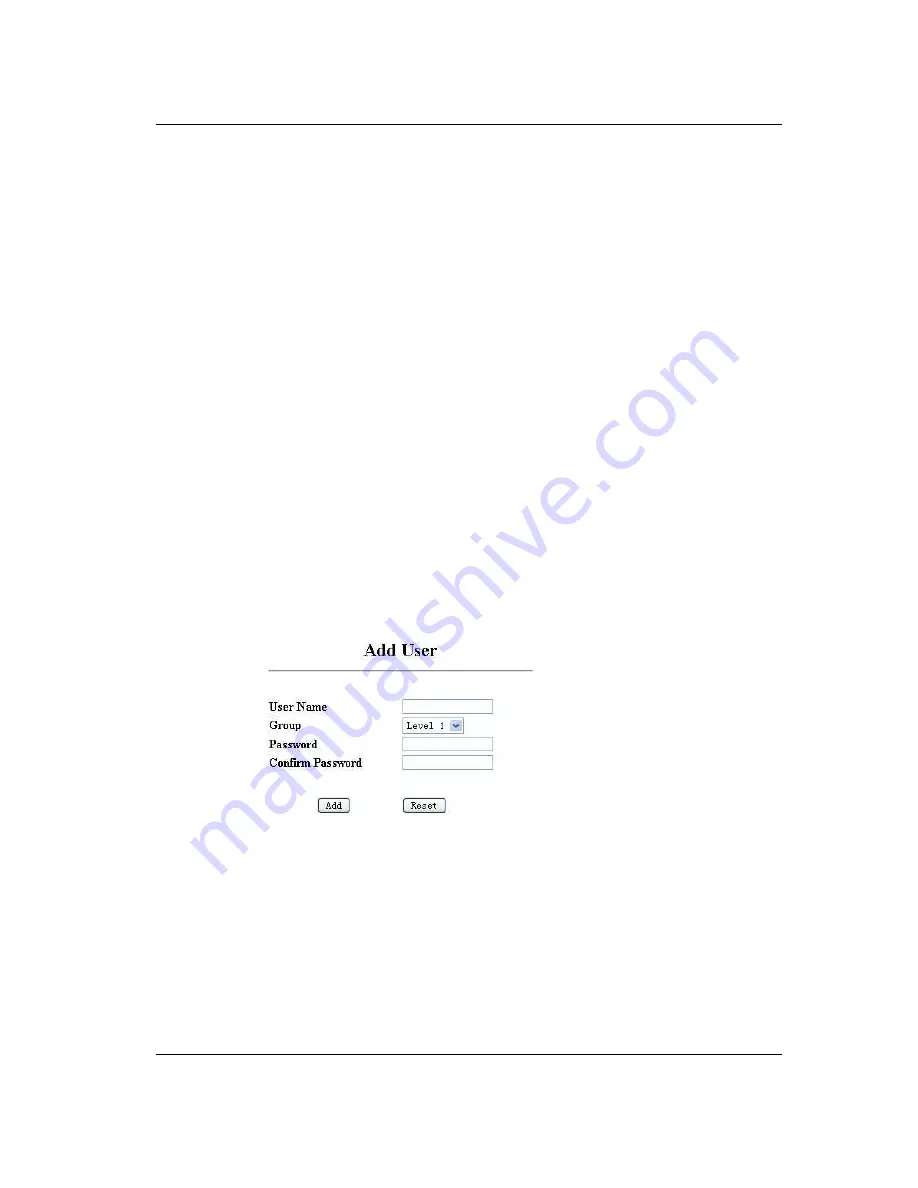
Add User 

The administrator may add new users to the system as follows: 


User ID

 Set user’s name 


Group

 Set the access class ( range: 1-4) 


Password—Set access password 


Confirm Password—Confirm the access password 


Configure via WEB 


1. Access the system and click the left column of the menu: 

>Administration 

>Maintenance 

>Add User 

2. Configure all relevant parameters. 

Summary of Contents for Challenger L Series

Page 1: ...Challenger L Series User Reference and Installation Manual WNI Global INC VERSION 2 0...

Page 2: ...y 1 16 1 9 2 ODU Specification summary 1 17 1 9 3 IDU Software Selectable Capacities 1 18 2 INSTALLATION 2 19 2 1 Unpacking 2 19 Challenger L ODU 2 19 2 2 Notices 2 20 2 3 PRE INSTALLATION NOTES 2 21...

Page 3: ...L Ethernet 100BaseTX Payload Connector 4 1 4 3 Challenger L STM 1 Payload Connector 4 2 4 4 Challenger L E 3 Payload Connector 4 2 4 5 NMS 10 100BaseTX Connector 4 2 4 6 ODU Connector 4 5 4 7 E1 Chann...

Page 4: ......

Page 5: ...lenger L series digital radio enables network operators mobile and private government and access service provides to offer a portfolio of secure scalable wireless applications for data video and Voice...

Page 6: ...technology offers to those involved in the design deployment and support of broadband fixed wireless networks Table 1 1 Key Benefits and Advantages of Challenger L Digital Radios Benefits Advantages...

Page 7: ...generating payload channel Lowers total cost of ownership 1 2 1 5 Ring Architecture Supports a ring consecutive point configuration thus creating a self healing redundancy that is more reliable than t...

Page 8: ...prehensive Link Network Management Software A graphical user interface offers security configuration fault and performance management via standard craft interfaces Suite of SNMP compatible network man...

Page 9: ...d Modulation concatenated with Reed Solomon Error Correction Built in Adaptive Equalizer Support of Voice Orderwire Channels Peak output power 24 dBm will vary with ODU and frequency plan Receive Sens...

Page 10: ...n the Challenger L IDU front panel Figure 1 2 Challenger L IDU LEDs Front Panel 1 0 Configuration 1 4 2 Front Panel Connections Please refer to the Figure 1 3 for an example of a Challenger L IDU fron...

Page 11: ...respect to the unit chassis ground A ground isolated supply may be used provided it will tolerate grounding of its most positive output The recommended power input is 44 to 52 V dc at 2 Amps minimum I...

Page 12: ...rface USB USB connector optional Voice Orderwire Connector Voice Orderwire Call Call button to alert operator at link partner Challenger L IDU of incoming Voice Orderwire call Voice Orderwire RJ 11 mo...

Page 13: ...he STM 1 optical interface STM 1 In BNC connector for the STM 1 electrical interface SC connector for the STM 1 optical interface E 3 Connection E 3 Out BNC connector for the E 3 interface E 3 In BNC...

Page 14: ...Telemetery IDU Controller Quad Mux MODEM FEC ASIC Modulation BPSK 256 QAM Adaptive Equalization 17 Taps FEC TCM Reed Solomon Digital IF West Secondary Modem Multiplexed Signal to ODU Quad Mux SWITCH...

Page 15: ...r L IDU and ODU with power A second redundant power supply may be added as an optional module The Modem Processor and its associated RAM ROM and peripherals control the digital and analog Modem operat...

Page 16: ...14 1 1 256 QAM TCM 7 8 15 16 1 1 Notes 1 Codeword byte length N 200 255 Message byte length K 184 253 check byte length N K 2 20 The RS encoding shall be programmable over the following ranges Codewor...

Page 17: ...r supply converts 48 Vdc to the DC voltage levels required by each component in the system 1 6 Consecutive Point Architecture The consecutive point network architecture is based upon the proven SONET...

Page 18: ...eplacing in ground fiber cable A typical consecutive point network consists of a POP and several customer sites connected using Challenger L units These units are typically in a building in an east we...

Page 19: ...r the resulting sparse deployment model is inappropriate for metropolitan areas In response to the need for a high density deployment model the Challenger L use a unique power control technique called...

Page 20: ...eatured MIB allowing for automation of data collection and network management 3 Via a command line client accessible from a terminal client connected to the serial port or telnet over the NMS Ethernet...

Page 21: ...increments 0 1 dB 0 1 dB 0 1 dB Guaranteed max power 24 dBm 22 dBm 14 dBm Spurious emissions 21 2 to 27 GHz 30 dBm 5 to 21 2 GHz 50 dBm 21 2 to 79 GHz 30 dBm 5 GHz to 21 2 GHz 50 dBm Frequency stabil...

Page 22: ...28 16QAM 32 0 0 1 0 1 9 3 2 Mixed E1 Ethernet SDH Capacities Mode Name Channel Bandwidth Modulation NxE1 n Ethernet Data Mbps STM 1 OC 3 n Ethernet NMS Mbps Ethernet plus Modes 78 78Eth 28MHz 28 128QA...

Page 23: ...ital Radio Challenger L IDU 1RU chassis 1 ODU with hardware 1 Manual or Soft copy on a CD 1 Test Data Sheet customer documentation 1 Figure 2 1 Challenger L Digital Radio Components Be sure to retain...

Page 24: ...r each frequency band and other applicable rules and precautions with respect to transmitters facilities and operations that may affect the environment due to RF emissions for each radio equipment dep...

Page 25: ...LE WARNING HIGH VOLTAGE IS PRESENT INSIDE THE ODU and Challenger L IDU WHEN THE UNIT IS PLUGGED IN TO PREVENT ELECTRICAL SHOCK UNPLUG THE POWER CABLE BEFORE SERVICING UNIT SHOULD BE SERVICED BY QUALIF...

Page 26: ...ring specific information about potential Digital Radio installation sites Cable and Installation Testing and installing Challenger L ODU cables and optional interface devices at installation sites Ch...

Page 27: ...Cables Mount and Align ODUs Perform Site Evaluation Configure Digital Software Defined IDUTM Perform Fast PDH Network Test Perform SDH Network Test Type of Network Installation Commissioning Complete...

Page 28: ...site evaluation RF and network design diagrams as required Binoculars Global positioning system GPS or range finder Compass Measuring tape and or wheel Digital camera Area map Aerial photograph if av...

Page 29: ...path from the desired location of the near Radio to the desired location of the far Radio To confirm Line of Sight Ensure that no obstructions are close to the transmitting receiving path Take into c...

Page 30: ...ds to be performed by an RF engineer The specific information required for each transmitter and receiver includes the following Transmitting and or receiving frequency Type of antenna Distance from Ch...

Page 31: ...t it is aesthetically pleasing to the environment and to the property owner Aesthetics must be approved by the property owner and the network engineer Take Site Photographs Sketch the Site 2 5 3 Criti...

Page 32: ...s Climate dry temperate hot humid Depending on the type of traffic carried over the link and the overall network design redundancy fade margin should be included to support the desired availability ra...

Page 33: ...rchase and install than smaller antennas and in some cases they require special equipment for installation due to narrower beamwidths They are also more easily affected by wind Only directional antenn...

Page 34: ...od Wall or Pole FCC Compliance Yes Collocation Aesthetics ODU Azimuth 60 degrees GPS Reading 80 21 48 Cable Lengths Alarm Interconnect Cable 250 feet Grounding Lighting Instructions Photographs Photo...

Page 35: ...ation Source PCS Tx and or Rx Tx Rx Frequency 2 1 GHz Distance from ODU 5 feet Owner Sprint PCS Azimuth 210 degrees Elevation 2 degrees downtilt Antenna Type Power Power 14W Parameters Example Informa...

Page 36: ...dust free environment that allows easy access to the rear grounding post as well as the front panel controls and indicators Air must be able to pass freely over the chassis Accessible for service and...

Page 37: ...nger L IDU Dimensions 2 6 1 4 Grounding the Challenger L IDU 1 Remove the nut and ring lug terminal from the Challenger L IDU optional Chassis GND stud located on the front panel 2 The provided ring l...

Page 38: ...s as supplied by the vendor Before heading out to the site a Make sure that you have the following tools and accessories NOTE The tools list should be regarded as a recommended list These tools are no...

Page 39: ...routing path pull the ODU IDU Interconnect cable from one unit to the other utilizing cable trays ducts or conduit as required Take care that the ODU IDU Interconnect cable is not kinked or damaged in...

Page 40: ...tor has screw clamp terminals that accommodate 24 AWG to 12 AWG wire The recommended wire size for construction of power cables under 10 feet in length supplying 48 V dc is 18 AWG The opposite end of...

Page 41: ...ds as per step 2 above Refer to Figure 2 4 Note that the Challenger L IDU does not have a power on off switch When DC power is connected the digital radio powers up and is operational There can be up...

Page 42: ...Version No V2 0 Figure 2 5 Challenger L IDU 1 1 Protection Front Panel Connections Power Input Redundant Power Supply NMS Ethernet ALARM Serial Interface USB Optional Voice Orderwire Call Button Inter...

Page 43: ...TBR final number dependent on ODU type Channelization 3 5 40 MHz Depending on band 28 40 MHz Depending on band Radio Interfaces Antenna N Type Rectangular Waveguide Depending on band N Type Rectangula...

Page 44: ...C Challenger L IDU Humidity 0 to 95 non condensing 0 to 95 non condensing ODU Humidity 100 All weather 100 All weather Altitude 15 000 feet 4572 meters maximum 15 000 feet 4572 meters maximum Physical...

Page 45: ...le PIN TYPE SIGNAL 1 POWER Power supply return IDU chassis ground 2 POWER 48 Vdc nominal 4 2 Challenger L Ethernet 100BaseTX Payload Connector RJ 45 Female PIN TYPE SIGNAL 1 OUTPUT TX 2 OUTPUT TX 3 IN...

Page 46: ...2 0 4 3 Challenger L STM 1 Payload Connector SC Duplex BNC Duplex TX RX 4 4 Challenger L E 3 Payload Connector BNC Duplex TX RX 4 5 NMS 10 100BaseTX Connector RJ 45 Female PIN TYPE SIGNAL 1 OUTPUT TX...

Page 47: ...al and its confidentiality is preserved Without the pre written consent from WNI Global anyone may not disclose extract cite or publish any part or all parts of this manual Version No V2 0 4 N A N A 5...

Page 48: ...ation 2 Form C Contacts are hardware jumper configurable to emulate TTL outputs PIN TYPE SIGNAL 1 OUTPUT TTL Alarm Output 1 21 INPUT O utput RS 232 RX TX 31 OUTPUT Input RS 232 TX RX 4 OUTPUT TTL Alar...

Page 49: ...cite or publish any part or all parts of this manual Version No V2 0 4 6 ODU Connector TNC coaxial female PIN TYPE SIGNAL Center I O 350 MHz TX IF 140 MHz RX IF 48 VDC Shield N A Shield Chassis GND 4...

Page 50: ...4 OUTPUT E1 Channel 16 Transmit Tip 5 OUTPUT E1 Channel 9 Transmit Tip 6 OUTPUT E1 Channel 10 Transmit Tip 7 OUTPUT E1 Channel 11 Transmit Tip 8 OUTPUT E1 Channel 12 Transmit Tip 9 OUTPUT E1 Channel 5...

Page 51: ...eceive Tip 38 INPUT E1 Channel 4 Receive Tip 39 INPUT E1 Channel 12 Receive Tip 40 INPUT E1 Channel 3 Receive Tip 41 INPUT E1 Channel 5 Receive Tip 42 INPUT E1 Channel 8 Receive Tip 43 INPUT E1 Channe...

Page 52: ......

Page 53: ...access Challenger L IDU 5 2 1 Local Access 5 2 1 1 Serial Port One may access Challenger L IDU via Serial Port with the following item required PC with Serial Port Challenger L IDU cable from DB 9 to...

Page 54: ...allenger L IDU Stranded cable or straight through cable IE5 5 or higher version Telnet or SSH Client program SNMP Manager 5 2 2 Telnet Access 5 2 2 1 Serial Port One may access Challenger L IDU via Se...

Page 55: ...is manual Version No V2 0 Telnet or SSH Client program SNMP Manager 5 3 Customer Interface 5 3 1 Overview 5 3 1 1 Overview of WEB Start WEB explorer eg IE Explorer Enter the IP address of to be linked...

Page 56: ...erface Ethernet Interface enter IP address to access Telnet SSH to prompt for access Serial Port access via RS232 with prompt for access Modem Interface Remote user may get his IP address from the dia...

Page 57: ...equired screen by pressing A B or C 2 Press the selected hot key to modify relevant parameter For example Press a or A and Enter to modify IP address 3 Sometimes one parameter contains more than one f...

Page 58: ...ual Version No V2 0 5 3 2 Customer Interface 5 3 2 1 Starting Information Refer to the above screen for the starting information of the customer interface One may get complete information about the pr...

Page 59: ...or all parts of this manual Version No V2 0 5 3 2 2 Status Panel 1 ALARM Alarm Status Red Light On Green light Off 2 MODEM Status of modulation and demodulation Lock Symbol Modulation Demodulation Loc...

Page 60: ...Local Equipment 10 Local Host Local equipment name 11 Remote IP IP Address of Remote Equipment 12 Remote Host Remote Equipment Description 5 3 2 3 General Network Configuration Used to configure netw...

Page 61: ...on No V2 0 Configure via WEB 1 Access WEB and click the menu column on the right Administration Network Configuration General 2 Current parameters of the Network may be displayed 3 Press Reset to get...

Page 62: ...n A Network Configuration A General 2 Current values of all relevant network parameters would be displayed 3 To modify any parameter one may press relevant hot key to modify and press Enter after modi...

Page 63: ...Perform the following tasks to configure E mail parameters 1 SMTP Enable Enable or disable Mail functionality 2 SMTP Server IP Configure the IP address of SMTP server 3 SMTP Port Configure SMTP port w...

Page 64: ...ersion No V2 0 Network Configuration E mail 2 Current values of all E mail parameter shall be displayed 3 Press Reset to get back the original value 4 Press Update to submit the modifications 5 Renew...

Page 65: ...4 In the modification process one may get back the original value by pressing Esc 5 Press the blank key to choose among the listed parameters and press Enter to confirm 6 Press Update to submit modif...

Page 66: ...rameter is not displayed it means the concerned value is not valid Configure via CLI 1 Access the main menu and perform the following tasks B Administration B Serial Configuration 2 Current values of...

Page 67: ...guration Modify security configurations of the system 1 HTTP Choose HTTP access mode 2 Command Line Interface Choose CLI access mode Configure via WEB 1 Access the system and click the left column of...

Page 68: ...yed 3 To modify any parameter one may press relevant hot key to modify and press Enter after modification confirmed 4 In the modification process one may get back the original value by pressing Esc 5...

Page 69: ...quipment Description 2 Host Name Name for local equipment 3 Model Number Number for the module 4 Owner Owner s name 5 Contact Contact information of the owner 6 Description Brief description of the eq...

Page 70: ...its confidentiality is preserved Without the pre written consent from WNI Global anyone may not disclose extract cite or publish any part or all parts of this manual Version No V2 0 Configure via CLI...

Page 71: ...to modify and press Enter after modification confirmed 4 In the modification process one may get back the original value by pressing Esc 5 Renew the page and display modified or current values 6 If an...

Page 72: ...rmation Set Date Time 2 Current values of all relevant parameter shall be displayed 3 Choose and modify all specific parameters 4 Press Update to submit modifications 5 Or press Reset to quit the modi...

Page 73: ...nd key to choose among the following option and press Enter to confirm the selection a Date Format b SNTP Server Enable 6 Renew the page and display modified or current values 7 If any modified parame...

Page 74: ...ract cite or publish any part or all parts of this manual Version No V2 0 Read via CLI Access the main menu and read specific parameters by pressing relevant hot key B Administration C Device Configur...

Page 75: ...Maintenance Re programming 2 All programs stored in the equipment may be displayed with the red mark beside on use programs 3 To switch any primary program to the secondary one click the program name...

Page 76: ...ry program press a or A select the target program and press Enter to confirm the switch Then the secondary program would be displayed 4 Press b or B to complete the switch 5 3 2 12 Add User The admini...

Page 77: ...User The administrator may delete any user of the system or modify any user s password User Name Choose the target user New Password Set new password Confirm Password Confirm new password Configure vi...

Page 78: ...any user s password one may press the blank key to select the target user in the menu of Change Password Press Enter to confirm to modify Enter new password and confirm the new password 3 To delete a...

Page 79: ...main menu and click the hot key to perform the following tasks B Administration C Maintenance B View Eventlog C Clear Eventlog 2 Press B to view the relevant record and C to clear the record 5 3 2 15...

Page 80: ...as the following B Administration C Reboot 2 To reboot any module one may first a or A then use the blank key to select it Press Enter to confirm the selection 3 Press b or B to reboot the selected mo...

Page 81: ...umn of the menu Link Configuration Configuration Summary View via CLI 1 Access the main menu and press the hot key as follows B IDU Configuration C Radio Link B Framer Summary 5 3 2 17 APC Configurati...

Page 82: ...t or all parts of this manual Version No V2 0 TX Power Minimum Minimum Transmit Power Step Size Step size of power adapting Update Far End Threshold Renew the remote thresholds Disabled off Enabled on...

Page 83: ...rmal operation status Configure via WEB 1 Access the system and click the left column of the menu Link Configuration Radio Link Link Configuration 2 Select ODU operation mode from the listed options a...

Page 84: ...r all parts of this manual Version No V2 0 5 Set the operation frequency in the specific range and click Next to the next step or click Back to the last sep to configure again 6 All configured setting...

Page 85: ...guration Radio Link ODU Power 2 Set proper TX power and click Update to confirm the value or click Reset to configure the value again 5 3 2 20 ODU Channel Set the ODU operation frequency One may use t...

Page 86: ...only be read and show the current alarm of the equipment View via WEB 1 Access the system and click the left column of the menu Analysis Alarms Active 5 3 2 22 Alarms History Alarms History may only b...

Page 87: ...l parts of this manual Version No V2 0 Configure via WEB 1 Access the system and click the left column of the menu Analysis Statistics Loop Back 2 Select one looptest type for LIU test interface type...

Page 88: ......

Page 89: ...mpetitive Local Exchange Carrier CMRR Common Mode Rejection Ratio CO Central Office Codec Coder Decoder CPE Customer Premise Equipment CPU Central Processing Unit CPFSK Continuous Phase Frequency Shif...

Page 90: ...ng FT1 Fractional T1 GPI General Purpose Input HP OpenView Hewlett Packard s network management product IC Integrated circuit IEC International Electrotechnical Commission IF Intermediate frequency IM...

Page 91: ...Printed circuit board PCM Pulse Code Modulation PGM Program PLL Phase Locked Loop POP Point of Presence PRBS Pseudo Random Bit Stream QAM Quadrature Amplitude Modulation QPSK Quadrature Phase Shift Ke...

Page 92: ...ansistor transistor logic TX Transmitter Vrms Volts root mean square Vp Volts peak Vp p Volts peak to peak VOIP Voice Over Internet Protocol VPN Virtual Private Network VRMS Volts root mean square VSW...

Page 93: ...7 0 90 1 1 400 44 1 8 0 88 9 1 600 42 9 9 0 87 9 1 800 41 9 10 87 0 2 000 41 0 11 86 2 2 500 39 0 12 85 4 3 000 37 4 14 84 1 3 500 36 1 16 82 9 4 000 34 9 18 81 9 4 500 33 9 20 81 0 5 000 33 0 25 79...

Page 94: ...ser Manual 6 6 This manual is provided by WNI Global and its confidentiality is preserved Without the pre written consent from WNI Global anyone may not disclose extract cite or publish any part or al...

Reviews: