3
Installation instructions Remote 3000 / 3010
2.1 Installing the lock
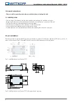
• The electronic lock has to be fixed with 4 x M6 screws in the prepared drillings in order to ensure a permanent hold.
• An independent loosening of the screws has to be avoided. It is recommended to put lock washers underneath the screw’s
head. To avoid malfunctions, turn the screws with a maximum turning force of 3.5 – 5 Nm.
• After the installation the lock’s bolt may not be loaded. The maximum bolt load is 2.5 N.
• The electronic lock is maintenance free in normal domestic and office surroundings. After approx. 10,000 closures it is
recommended to carry out a security and functional test of the electronic lock.
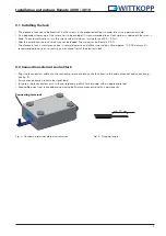
Connecting terminal
2.2 Connection external control/lock
• Plug single conductors cable into the connecting terminal plate on the lock from/to the external control and check fixing
(see fig. 2).
• Ensure enough traction relief to the signal lead.
• To loosen single conductors push in the corresponding clutch fork (orange) with an appropriate tool.
• Keep cable away from sharp edges and moving boltwork components and fix it permanently.
Fig. 3: Connecting terminal plate electronic lock
Fig. 4: Stripping length
min. 10 mm

