


4
1.6
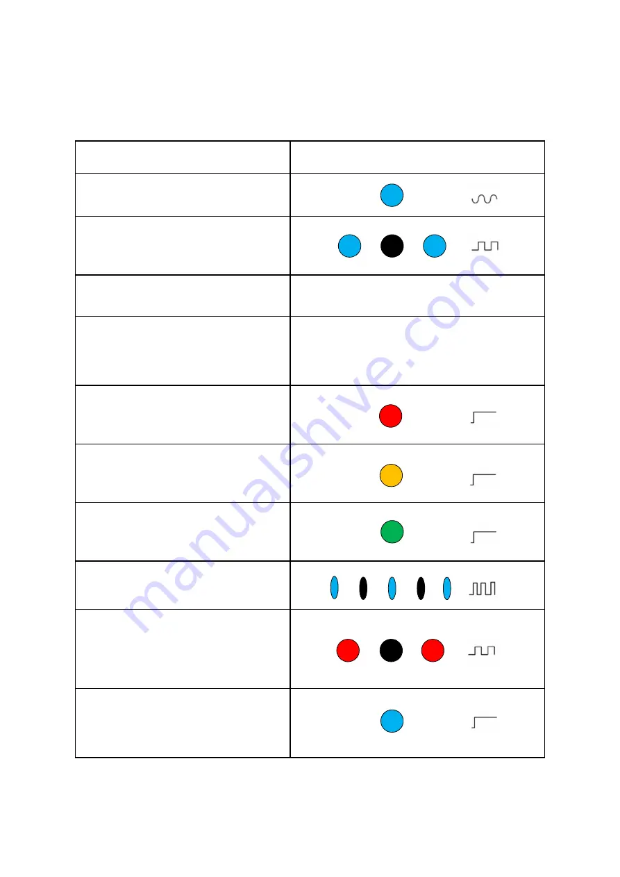
LED Notification Guide
Status
Bottom LED
Device is powering up
Soft fade in-out blue
Bluetooth
®
pairing mode
(INSTALLATION MODE)
Pairing starts automatically once the device is
powered on.
Bluetooth
®
is paired
LED stops blinking blue
Activation complete
(INSTALLATION MODE)
The device has successfully activated and
established an LTE connection, and will start
searching for a 5G signal.
No 5G signal
(INSTALLATION MODE)
The Gateway did not immediately detect a 5G
signal after activation.
Poor 5G signal
(INSTALLATION MODE)
A 5G signal is detected after activation, but
signal strength is inadequate.
Acceptable 5G signal
(INSTALLATION MODE)
The detected 5G signal is good enough for
installation to continue.
Firmware update/factory reset in progress
The device is in the process of
updating/resetting software.
Error (Fault)
A hardware/software issue has occurred
Possible issues:
• CPE is broken
• Firmware is faulty
• Internet connection has been lost
Device is operating normally
(REGULAR USAGE MODE)
Device setup is complete and an Internet
connection has been established. The LED is
solid blue.


