3
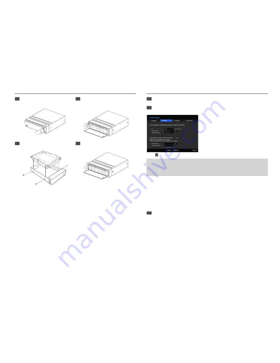
Installing the HDD
1
Press the <
PUSH
> button on the front to open the
front cover.
2
After pressing the blue button in the HDD bracket,
pull it manually to separate the HDD bracket from
the main body.
REC
1
2
3
4
5
6
7
8
9
10
11
12
ALARM
POW
ER
BACK
UP
NETWO
RK
RAID
USB
HDD
3
Mount a HDD in the HDD bracket and screw it in
using the screws provided.
4
Once the HDD is mounted in the bracket, push the
bracket into the main body and close the front cover.
J
`
If you are adding a new or previously used HDD to this product in addition to the HDD(s) originally installed, format the new HDD
manually in the set before use.
`
For replacement or installation of an additional HDD you must contact your dealer or our customer center.
Install Wizard
1
Select the language
Select your preferred language.
2
Set Password
Set a password.
※
Click icon to see the password rule
8 ~ 9 characters
: All combination of English character, Digit, Special character
10 ~ 15 characters
: Two combination of English character, Digit, Special character
※
Not allowed to use same characters with ID
※
Not allowed to use 4 or more continuative or repeated characters
2-1. Setting Camera Password
You can change the password of the camera one step.
If the password of the camera is the default password set in the factory, enter a new password to change it. The
password will be changed, and the new password will be registered.
If the password of the camera is not the default password set in the factory, enter the current camera password.
The current camera password will be registered.
- New Password : Input a new password according to the password setting rules.
- Confirm Password : Input the new password again.
`
A camera password registered with ONVIF and RTSP cannot be changed.
3
Set up Network
• DHCP server : If the DHCP server is set to enable, an IP is automatically assigned to the camera.
• Network 1 (Camera) /Network 2 (Camera) : Connects to the camera and receives the video feed from the
camera.
`
When a UTP cable is connected, UTP is displayed on the screen, and when an Fiber Optic Cable is connected, OPTIC is displayed
on the screen.
• Network 3 (Viewer) : This is a port for transmitting an image to the webviewer.
• Network 4 (iSCSI) : This is a port for connecting an external iSCSI.
• Network 1 / Network 2 / Network 3 / Network 4 Setup
- IP Type : Choose the network connection method.
- IP Address, Subnet Mask, Gateway, DNS
※
For more details on network settings, refer to the User manual.
► To use a simple intranet, click <
Next
>.


