background image

English _

17


!

INST

ALLA

TION & CONNECTION

POWERING AND NETWORKING

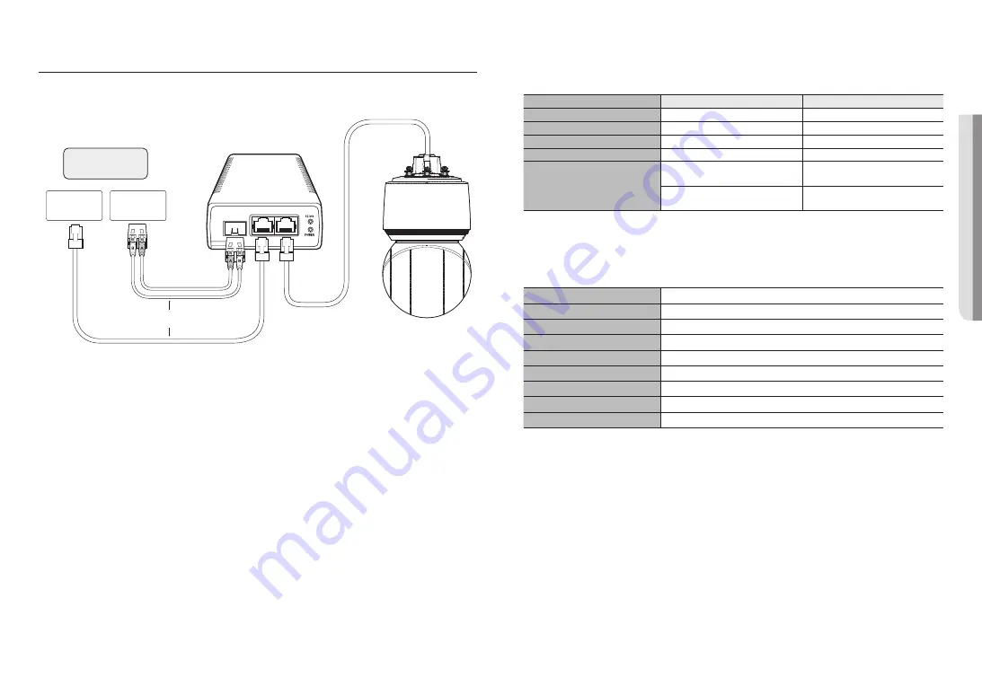
To use XNP-9250R/XNP-8250R/XNP-6400R models, connect the HPoE injector shipped together.
To use XNP-9250/XNP-8250/XNP-6400 models, connect a PoE+-supported router or PoE+ injector.

Switch

SFP Port 

Switch

SFP module

External internet

OR


J


`

The product cannot be used at -40°C or below ambient temperature.


`

The product may not be defrosted depending on the installation area at -40°C.


`

After the product is left alone under a low temperature environment, it will take up to 2 hours to normally operate.


`

If the product is turned on after being exposed to -20°C or below environment for some time, reset the time.


`

Use the provided HPoE injector when connecting power and network. (XNP-9250R/XNP-8250R/XNP-6400R)


`

Use a PoE+ device that complies with the IEEE 802.3at standard. (XNP-9250/XNP-8250/XNP-6400)


`

If you connect using an PoE+ -enabled router, you don’t need a separate power supply cable to power it on.(XNP-9250/ 
XNP-8250/XNP-6400)


`

Use only either one of network cable or fiber optic cable for connection.

Network Cable Specification

Item

Contents

Remark

Connector

RJ45 (10/100BASE-T)

Ethernet

10/100BASE-T

Cable

UTP Category 5e

Max Distance

100 m

DC Resistance ≤ 0.125 Ω/m

PoE Support

HPoE 

(XNP-9250R/XNP-8250R/XNP-6400R)

PoE+ 

(XNP-9250/XNP-8250/XNP-6400)


M


`

Use an STP cable to increase the protection from thunderstroke damage.

SFP port Specification

Support SFP Voltage

3.3 V Typical

Support SFP Current

300 mA Max.

Support SFP Cage

Standard mini-SFP Cage(for 6.5 mm pitch SFP)

Support SFP Port Type

LC Type

Required SFP Speed

1250 Mbps(For 1000 Mbps Ethernet)

Required SFP’s BER(Bit Error Rate)

Max 10

-12

Transmission Method(Optical)

Mode Depends on SFP Module

Optical Mode(Long/Short Wave)

Mode Depends on SFP Module

Cable Insertion Loss(dB)

Mode Depends on SFP Module


J


`

The connection/disconnection of the SFP module must be made only when the power is off.


`

A kink in the optical cable may disrupt the connection for communication.


`

Do not directly look at the optical cable. It can damage your eyes.

Summary of Contents for CT-XNP-8250

Page 1: ...NETWORK CAMERA User Manual XNP 9250R XNP 9250 XNP 8250R XNP 8250 XNP 6400R XNP 6400 ...
Page 2: ... correctness of the contents in this document but no formal guarantee shall be provided Use of this document and the subsequent results shall be entirely on the user s own responsibility Hanwha Techwin reserves the right to change the contents of this document without prior notice Designandspecificationsaresubjecttochangewithoutpriornotice TheinitialadministratorIDis admin andthepasswordshouldbese...

Page 3: ...wer 18 If you use excessive force when installing the product the camera may be damaged and malfunction If you forcibly install the product using non compliant tools the product may be damaged 19 Do not install the product in a place where chemical substances or oil mist exists or may be generated As edible oils such as soybean oil may damage or warp the product do not install the product in the k...

Page 4: ...isted device with the output evaluated as a Limited Power Source as defined in UL60950 1 or PS2 as defined in UL62368 1 XNP 9250 XNP 8250 XNP 6400 Unit is intended for installation in a Network Environment 0 as defined in IEC TR 62102 As such associated Ethernet wiring shall be limited to inside the building Please read the following recommended safety precautions carefully Do not place this appar...

Page 5: ...K CONNECTION AND SETUP 19 19 Connecting the Camera Directly to Local Area Networking 19 Connecting the Camera Directly to a DHCP Based DSL Cable Modem 20 Using Device Manager 20 Automatically searching camera 20 Configuring IP address 21 Manually registering camera 21 Automatically configuring IP 22 Port Range Forward Port Mapping Setup 23 Connecting to the Camera from a Shared Local PC 23 Connect...

Page 6: ...rs RECOMMENDED MICRO SD SDHC SDXC MEMORY CARD SPECIFICATIONS Recommended capacity 16GB to 1TB MLC type required Recommended Manufacturers SanDisk Transcend Product Type High endurance The compatibility varies depending on the card manufacturers and types J J Micro SD card can support up to 1 TB if two slots are used Each slot supports up to 512 GB and one slot cannot support 1 TB by itself NAS REC...

Page 7: ...r network cable installation Torx L wrench 1 Used to open the micro SD card slot HPoE injector 1 Connects power supply and network XNP 9250R XNP 8250R XNP 6400R Power cord 1 Connects to HPoE injector NETWORK I O BOX SEPARATELY SOLD PRODUCT Appearance Item Name Description Model Name Network I O box External connection device for camera s alarm and audio I O SPM 4210 OPTIONAL ACCESSORIES FOR INSTAL...

Page 8: ...oming light to control the IR LED c Heater At a certain temperature below the threshold it automatically operates or you can turn it on manually in the web viewer d Lens Lens for the camera e Reset button The button restores all camera settings to the factory default Press and hold for about 5 seconds to reboot the system J If you reset the camera the network settings will be adjusted so that DHCP...

Page 9: ...the Device Manager program to change the basic network settings such as IP address Subnet mask Gateway etc before you can connect to the network d Micro SD Card slot Compartment for the Micro SD card Mounting surface Item Description a Cable bushing A waterproof rubber cap which allows a network cable to go through it b Safety wire hook Hang this hook on the safety wire of the mount when installin...

Page 10: ...h excessive force it may cause damage to the camera due to malfunction Forcing assembly using non compliant tools may damage the product Inserting a Micro SD card 1 Unfasten screw on the Micro SD card cover by turning them counterclockwise using the Torx L wrench x4 TR10 J J Disconnect the power cable from the camera before inserting the Micro SD card When it rains or the humidity is high insertio...

Page 11: ...hown in the diagram to eject the Micro SD card from the slot J J Before removing the Micro SD card in Storage set the device to Off and press the Apply button and turn the camera off If you turn off the camera or remove the Micro SD card that contains data from the product the data may be lost or damaged Preparing Installing Camera Mount For installation guidelines for mounts refer to the installa...

Page 12: ...ng is torn use the extra cable bushing provided 4 For waterproof protection pull down the cable below the cable bushing as shown in the figure below 9 10 cm Installing using wall pole mount J J Connect the power only after installation is complete Supplying power while the installation is in progress may cause fire or damage the product 1 Hang the safety wire of the wall pole mount on the safety w...

Page 13: ...ed in J J The length and width of the cable bushing are different Check the shape and plug it in the right direction 4 Install the bushing clip Let the arrow mark on the clip point in the direction of the safety wire hook and click each side into place one at a time 5 After aligning the installation direction guides of the camera and wall pole mount push the main cover upward and turn it countercl...

Page 14: ...screws on the inside of the Wall Pole Mount TR30 7 Join the top cover of the wall pole mount Installing using ceiling or parapet mount 1 Hang the safety wire of the mount on the safety wire hook of the product Safety wire hook Safety wire 2 Connect the network cable to the network port ...

Page 15: ...e different Check the shape and plug it in the right direction 4 Install the bushing clip Let the arrow mark on the clip point in the direction of the safety wire hook and click each side into place one at a time 5 After aligning the installation direction guides of the hanging mount push the main cover upward and turn it counterclockwise until it is secured 6 Tightly fasten the 3 mounting screws ...

Page 16: ...Parapet Mount SBP 156LMW Joined with mounts other than official product mounts If you use hanging mount you can install the camera onto any mount other than the official product mount Hanging Mount SBP 156HMW Wall Mount SBP 300WMW Hanging Mount SBP 156HMW Ceiling Mount SBP 300CMW Hanging Mount SBP 156HMW Parapet Mount SBP 300LMW ...

Page 17: ...er supply cable to power it on XNP 9250 XNP 8250 XNP 6400 Use only either one of network cable or fiber optic cable for connection Network Cable Specification Item Contents Remark Connector RJ45 10 100BASE T Ethernet 10 100BASE T Cable UTP Category 5e Max Distance 100 m DC Resistance 0 125 Ω m PoE Support HPoE XNP 9250R XNP 8250R XNP 6400R PoE XNP 9250 XNP 8250 XNP 6400 M M Use an STP cable to inc...

Page 18: ...ately sold Network Speaker Microphone SPM 4210 Alarm Warning lamp Sensor M M For more information on the network I O box see the manual for the network I O box You can set the network I O box in Camera web viewer Setup Event I O box menu Connect only one camera per network I O box The product may malfunction if more than one camera is connected ...

Page 19: ...To change the IP address use the Device Manager For further details on Device Manager use refer to Using Device Manager Page 20 CONNECTING THE CAMERA DIRECTLY TO A DHCP BASED DSL CABLE MODEM 1 Connect the user PC directly with the network camera 2 Run the Device Manager and change the IP address of the camera so that you can use the web browser on your desktop to connect to the Internet 3 Use the ...

Page 20: ...ministrator HTTP Port Used to access the camera using the Internet browser defaulted to 80 RTSP Port A port that controls real time streaming The initial value is 554 If using a Broadband Router IP Address Enter an address falling in the IP range provided by the Broadband Router ex 192 168 1 2 254 192 168 0 2 254 192 168 XXX 2 254 Subnet Mask The Subnet Mask of the Broadband Router will be the Sub...

Page 21: ...k OK MANUALLY REGISTERING CAMERA If the camera cannot be found using search function the camera can be registered remotely by manually inserting IP information if the camera is connected to external network 1 Click Add Devices Manually Add Device at the main page of device manager 2 Insert the range of IP address that you search 3 Select the Model Name of the camera that you register and insert HT...

Page 22: ...orwarding setting is an example of setting CISCO IP router The settings may differ depending on the connected Broadband Router model For more information refer to the user manual of the applicable router Setting up Port Range Forward for several network cameras You can set a rule of Port Forwarding on the Broadband Router device through its configuration web page A user can change each port using ...

Page 23: ...a remote computer that is not in the Broadband Router s network cluster is not allowed users can access cameras within a Broadband Router s network by using the camera s DDNS URL 1 Before you can access a camera in the Broadband Router network you should have set the port range forward for the Broadband Router 2 From the remote PC launch the Internet browser and type the DDNS URL address of the ca...

Page 24: ...m in support of the UPnP protocol 2 Click the camera name for search In the Windows operating system click the camera name searched from the network menu The login window is displayed Connecting via Bonjour 1 Run the client or operating system in support of the Bonjour protocol 2 Click the camera name for search In the Mac operating system click the camera name searched from the Bonjour tab of Saf...

Page 25: ...LOGIN Whenever you access the camera the login window appears Enter the User ID and password to access the camera 1 Enter admin in the User name input box The administrator ID admin is fixed and can not be changed 2 Enter the password in the Password input field 3 Click Sign in If you have logged in successfully you will the Live Viewer screen J J When you access the camera web viewer pay special ...

Page 26: ... without formatting the default folder saved or used Confirm that you used recommended NAS equipment TROUBLESHOOTING PROBLEM SOLUTION No video is displayed when accessing the plug in free webviewer on Safari via HTTPS On the authentication popup window prompted when initially accessing https click View Authentication Certificate and select the Always trust when connecting to the designated webview...

Page 27: ...r household waste at the end of their working life Where marked the chemical symbols Hg Cd or Pb indicate that the battery contains mercury cadmium or lead above the reference levels in EC Directive 2006 66 If batteries are not properly disposed of these substances can cause harm to human health or the environment To protect natural resources and to promote material reuse please separate batteries...

Page 28: ......

Reviews: