background image

WPS-765-DOM-AH Installation Manual

9

 © 2014 Wirepath Surveillance

Step 2. Mount the Camera

Using Mounting Accessories

Mount the accessory according to its instructions, make 

wiring connections, and mount the camera. Then, 

continue these instructions below at 

Step 3 

to complete 

camera installation

.

Surface Mounting

A.  Use the included template to mark the screw 

locations for mounting.

B.  Connect the camera to the wiring and move it 

into position. Avoid pinching the wires between the 

camera and the mounting surface.

C. Use 3 of the included screws to secure the camera. 

Insert the screws through the black mounting hole 

gaskets and hand-tighten them evenly.

Step 3. Adjust Focus, Zoom, and Menu Settings

See “Camera Operation Setup” beginning on the 

next page for instructions.  Set the focus and zoom 

adjustments, and adjust the OSD Setup Menu options as 

needed.  Disconnect the test adapter after completing 

adjustments.

Step 4. Close the Camera

DO NOT remove the factory-installed silica desiccant packet in the camera.

A.  Before closing the camera, remove 

the spare silica packet from its 

sealed foil package (taking care 

not to rip the inner packet) and 

place it inside the camera, out 

of the lens’ field of view. 

Do not 

remove the existing silica gel 

packet strapped inside the camera.

B.  Close the camera dome and use 

the 3mm Allen wrench to tighten 

the screws evenly. 

Remove the 

outer dome protective film last.

Factory Silica Pack


(attached to wire)

Place New Pack 

Behind Gimbal

Summary of Contents for WPS-765-DOM-AH

Page 1: ...CAMERA DOME INSTALLATION MANUAL Review manual thoroughly before installation Retain for future reference WPS 765 DOM AH...

Page 2: ...tes under temperature conditions between 40 F and 140 F 3 Do not mount the camera directly facing bright light sources Exposing the camera to strong light over long periods of time will damage the cam...

Page 3: ...2 6 2 1 OSD Joystick Test Adapter 12 6 2 2 How to Reset or Save Settings 12 6 3 OSD Menu Structure Outline 13 6 4 OSD Setup Menu Settings 15 6 4 1 SCENE SELECT 15 6 4 2 Advanced Menu Sub settings for...

Page 4: ...al 6 4 2 15 COMMUNICATION 25 6 4 2 16 LANGUAGE 25 6 4 2 17 VERSION 25 6 4 2 18 MAINTENANCE 26 6 4 3 EXIT MENU 27 7 Troubleshooting 28 8 Specifications 29 9 Dimensions 30 10 5 Year Limited Warranty 30...

Page 5: ...d off to ensure the camera operates within an optimum temperature range and helps to minimize condensation inside the housing at low temperatures The heater automatically activates at 50 F and deactiv...

Page 6: ...1 3mm Allen key 1 Foam gasket 1 Paper mounting template 1 Installation manual 1 Spare silica packet in vacuum sealed bag NOTE A POWER SUPPLY IS NOT INCLUDED WITH THIS CAMERA The PS 12DC 1A or WPS PS m...

Page 7: ...18 AWG Calculate based on voltage wire length 12V DC or 24V AC 1A minimum Included WPS ACC PWR M is illustrated to demonstrate the correct polarity for power 2 BNC Video Output Required Install coaxia...

Page 8: ...f a mounting accessory is being used unpack the accessory and become familiar with its installation and use B Apply the self adhesive foam gasket to the base of the camera C If the camera will be conn...

Page 9: ...tighten them evenly Step 3 Adjust Focus Zoom and Menu Settings See Camera Operation Setup beginning on the next page for instructions Set the focus and zoom adjustments and adjust the OSD Setup Menu...

Page 10: ...mera location for viewing adjustments 5 2 Using the Test Adapter Connect the yellow BNC adapter to a video monitor to view the menu Use a BNC RCA adapter to connect to a TV s yellow Composite input Co...

Page 11: ...custom text options choose whether or not to display options like camera ID and where to position overlaid text Configure RS485 communicate between cameras and DVRs or other security and automation s...

Page 12: ...etup is detailed in section 3 1 Wiring Connections on page 7 Enter RS485 command Set Preset 95 to turn on the OSD menu 6 2 1 OSD Joystick Test Adapter 6 2 2 How to Reset or Save Settings See section 6...

Page 13: ...SH N A USER1 B GAIN R GAIN USER2 B GAIN R GAIN MANUAL LEVEL PUSH LOCK N A HLC BLC OFF N A HLC CLIP LEVEL BLC N A WDR ATR EX OFF N A ATR EX CONTRACT CLEAR FACE WDR CONTRACT CLEAR FACE DNR LEVEL DAY NIG...

Page 14: ...M OFF ON MAG PAN TILT DIS OFF ON PRIVACY MASK AREA SEL DISPLAY POSITION COLOR TRANSP MOSAIC MOTION DET OFF ON DETECT SENSE INTERVAL BLOCK DISP MASK AREA MOTION AREA AREA SEL AREA MODE TOP BOTTOM LEFT...

Page 15: ...OFF SYS SETTING Preset Modes FULL AUTO default This mode is useful for applications where lighting conditions may change often or rapidly This is the recommended setting for most applications INDOOR T...

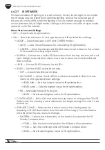
Page 16: ...ically amplifies the video signal during low light conditions Use this setting to increase contrast in dimly lit parts of the scene Select from FIX MANUAL or AUTO and enter the sub menu for advanced s...

Page 17: ...NMENT Select from AUTO INDOOR SUNNY or SHADE to match the conditions of the scene PUSH Adjusts white balance value dynamically for deeply colored objects and contrasting images based on how fast the i...

Page 18: ...appear as a silhouette but BLC will adjust contrast for more detail BLC is ideal where the field of view is focused close to the camera 6 4 2 4 WDR ATR EX Wide Dynamic Range Adaptive Tone Reproduction...

Page 19: ...se in the picture can be too high to see details AUTO This mode utilizes a sensor on the camera to determine the level of light hitting the sensor BURST When On video signal maintains the color burst...

Page 20: ...allows one area to become more illuminated than another LEVEL Set the IR LED intensity for all LEDs IR LED Set the IR LED activation mode OFF Deactivate LEDs at all times DAY NIGHT Allows the IR LEDs...

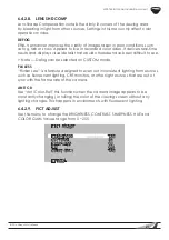
Page 21: ...ficult to see Note Defog can be selected on CUSTOM mode FLK LESS Flicker Less is a feature designed to even out inconsistent lighting from sources such as fluorescent lighting CRT monitors or other li...

Page 22: ...ng and or flickering of images Pivot the joystick left or right to set to OFF or ON No further settings are necessary 6 4 2 12 PRIVACY MASK SETUP Privacy mask settings allow for up to 15 different sur...

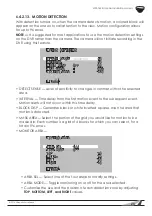
Page 23: ...evel of sensitivity to changes in contrast within the selected area INTERVAL Time delay from the first motion event to the subsequent event Motion alerts will not occur within this time delay BLOCK DI...

Page 24: ...trol the Iris Video allows the camera to monitor the image for lighting conditions and subsequent Iris control MODE The camera handles the size of the Iris opening Open is fully open closed is fully c...

Page 25: ...to identify the camera on the RS485 loop Note Each device in the RS485 connection MUST be set to a unique address number for proper RS 485 communication BAUDRATE Scroll left or right to choose a baud...

Page 26: ...surrounding pixels to be feathered in to fix the dead pixel MANUAL COMP REGISTRATION REG POINT OFF CURSOR COLOR WHITE BLINK OFF REG NUMBER 0 64 RETURN CAMERA RESET Factory resets the camera cannot be...

Page 27: ...on in the EXIT menu If adjustment to the camera s settings results in poor picture quality settings may be discarded NOT SAVE EXIT MENU PLEASE CHOOSE SAVE NOT SAVE CANCEL BACK SAVE Save all current se...

Page 28: ...essary clean with a soft clean eyeglasses cloth Check if the camera is facing bright lighting If so change the viewing position away from the light source If a device exists between the camera and scr...

Page 29: ...ter Yes OSD Yes WDR True WDR DNR 3D DNR Minimum Illumination 0 03 Lux color 0 00003 Lux Sens up Highlight Compensation Yes Auto Gain Control Yes Back High Light Compensation Yes White Balance Yes Lens...

Page 30: ...o be defective in material or workmanship under normal conditions of use This warranty shall not apply to products which have been abused modified disassembled or improperly installed Products to be r...

Page 31: ......
Page 32: ...140818 1230 2014 Wirepath Surveillance...

Reviews: