© 2014 Wirepath™ Surveillance Ver. 140718-1740
Support: (866) 838-5052
Package Contents
•
(1) WPS-300-BUL-IP Camera
•
(1) WPS-ACC-PWR-M Power Adapter
•
(1) Female-Female RJ45 Adapter
•
(1) 3mm Allen key
•
(4) Screws & Wall Anchors
•
(1) Quick Start Guide
I. Hardware Setup
(See other side for software and network setup)
WPS-300-BUL-IP
IP Surveillance Cameras
Quick Start Guide
IMPORTANT! BEFORE GOING TO JOB SITE:
Visit the Support Tab on the product page for this
camera at www.SnapAV.com. Download the latest
support files to your PC:
• Installation Manual
•
IP Installer utility software
•
Latest firmware (if available)
Contact the Tech Support team from the job site for help
with any part of setup:
Call: 866-838-5052
Email: [email protected]
Camera Cabling and Power
Install cabling between the camera and the LAN connection (and power source if not PoE powered)
Needed for this step:
Cables and connectors as indicated below, tools and connectors for terminations
Cable recommendations:
Network Connection -
The camera must
be connected to a LAN port using cable
that meets TIA/EIA Category 5e standards.
Test the cable after termination if possible.
PoE Power -
If the network equipment
supports
PoE standard IEEE 802.3af
then
power can be provided on the Cat5e/6
connection.
12V DC Power -
If PoE is not used, power
must be supplied using the external power
connector. The correct cable size must be
used to prevent voltage drop.
Requirements for Network Cable:
•
Type: Cat5e/6+ ONLY
•
Terminations: 568B recommended
• Max Length: 100 meters (328 feet)
Requirements for PoE Equipped Port:
• Voltage: 44V DC
•
Wattage: 15.4W
•
Amperage: 350mA
Requirements for Power Supply:
• Voltage: 12V DC
• Wattage: 12W
• Amperage: 1A
Thank you for purchasing a Wirepath™ IP Surveillance Camera. This
Quick Start Guide page shows the basics of installing the camera and
connecting to it from the local network.
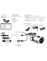
a. Install an accessory mount over the
wiring (if applicable). Then connect
the camera to the wiring as seen in the
diagram below.
Aiming Adjustments
A. Horizontal rotation
B. Swivel left or right
C. Tilt viewing angle
Mounting and Adjustments
A
B
C
Needed for this step:
3mm Allen Wrench, Phillips screwdriver for mounting screws, or tools for accessory mount screws (if used)
Internet
1
2
3
4
5
6
7
8
NC
NO
C OM
RS-485
ALARM IN
HDMI OUTPUT
HDMI
VGA
RELAY
ETHERNET
GND
GND
VGA OUTPUT
12V DC 6A
INPUT
WPS-ACC-PWR-M
Power Adapter
Female-to-Female
RJ45 Adapter
An NVR may be connected to the network for
recording and playback of camera footage
Router
Gigabit Switch
Cat5e/6+
12V DC Power Supply
(if PoE is not used)
b. Mount the camera using 3 of the 4
included screws and anchors, or install
the camera on the accessory mount.
Make adjustments last.
IMPORTANT!
The reset wires must remain
separately insulated to avoid accidental resets.
See the manual for camera reset instructions.


