background image

8

MIG WELDING GUN OPERATION MANUAL

7.0 TROUBLESHOOTING

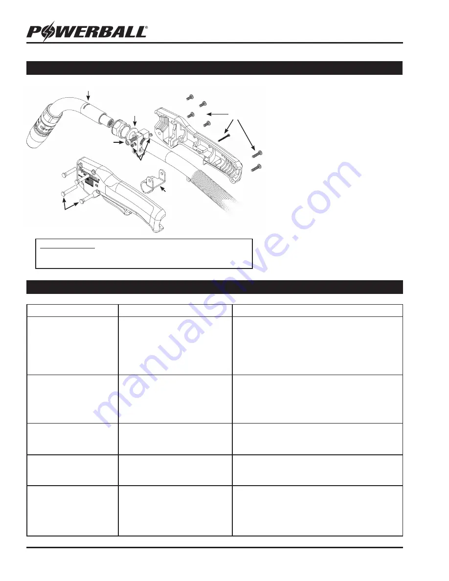
6.2  GOOSENECK REPLACEMENT INSTRUCTIONS

1.  Ensure power supply is OFF. Remove    

  the 7 handle screws from the right side 

  of the handle. Pull the hook attachment  

  pin to separate the two halves of the 

 handle.

2.  Loosen the gooseneck clamp bolt and 

  the two set screws.

3.  Remove gooseneck by turning 

  counterclockwise. Keep the insulating 

  washer at the base of the neck.

4.  Slide the insulating washer onto the 

  base of the new gooseneck. Install neck 

  assembly by turning clockwise.

5.  Secure the neck in place by tightening  

  the clamp bolt and two set screws. 

6.  Re-assemble handle with the 7 screws 

  and 4 attachment pins.

Handle Screws

(7)

Torch Hook

Attachment Pins

(4)

Gooseneck

Gooseneck 

Clamp Bolt

Set Screws

Insulating 

Washer

Problem

Potential Causes

Solutions

Wire will not feed or feeds 

erratically

• Poor connection to wire feeder
• Feeder drive roll problem
• Bad microswitch in trigger
• Worn torch liner
• Burn back in contact tip
• Wrong size torch liner or tip

Inspect all cables connected to wire feeder and ensure 

they are secure and in good condition. Check drive rolls 

for proper size and tension. Inspect torch liner for wear 

and build-up, replace as needed. Replace contact tip if a 

burn back has occurred. If feeder is set up properly and 

wire path is clear, the microswitch on the gun trigger may 

need replacing.

Burn-back at contact tip

• Improper wire feed speed
• Improper voltage for application
• Poor wire feed
• Improper wire stick-out
• Bad ground

Check welding parameters and ensure feed speed and 

voltage are set properly for your welding application. 

Adjust wire stick-out if necessary. Inspect cables to 

ensure proper grounding. Ensure wire delivery path does 

not have excess friction.

Erratic arc

• Bad contact tip
• Poor wire feed
• Build-up in liner

Inspect contact tip for wear and replace as needed. 

Check liner and wire delivery path for any build-up or 

wear. Replace liner or conduit as needed.

Weld porosity

• Plugged or damaged diffuser
• 

Poor gas flow

• Bad nozzle/insulator

Inspect diffuser for damage or debris, replace as needed. 

Check gas supply and gas lines for proper gas flow. If 

nozzle is badly worn, replace as needed.

Excess spatter

• Improper welding/gas parameters
• Tip not installed properly
• Bad nozzle/insulator
• Poor anti-spatter performance

Adjust welding parameters and gas mixture so it is 

optimized for your welding application. Check tip for 

proper installation and torque (see section 6.0). Replace 

nozzle as needed. Try a different anti-spatter - Blue 

Magic® Anti-Spatter from Wire Wizard® is recommended 

for best performance.

TOOLS REQUIRED:

Phillips Screwdriver   

   5/32” Allen Wrench

Small Crescent Wrench 

   3/32” Allen Wrench

Summary of Contents for Powerball

Page 1: ...HIGH PERFORMANCE MIG WELDING GUNS OPERATION MANUAL For 300 and 400 Amp Semi automatic MIG Guns ELCo Enterprises Inc Jackson Michigan USA Service Support 517 782 8040 www wire wizard com ...

Page 2: ...CTION 3 1 1 Warranty 3 1 2 Product Registration 3 2 0 SAFETY PRECAUTIONS 4 5 2 1 Welding and Safety Operating References 5 3 0 DUTY CYCLE SPECIFICATIONS 6 5 0 OPERATION 6 5 1 Trigger Pull Adjustment 6 6 0 CONSUMABLES REPLACEMENT 7 6 1 Torch Liner Replacement 7 6 2 Gooseneck Replacement Instructions 8 7 0 TROUBLESHOOTING 8 8 0 REPLACEMENT PARTS LIST 9 9 0 TORCH CONSUMABLES ACCESSORIES 10 TABLE OF C...

Page 3: ...e value of the defective product within the warranty period Buyer accepts all responsibility for compliance with any all Local State and Federal Laws or Regulations including Regulations of Foreign Governments No equipment shall be returned to ELCo without a Return Authorization Number Upon evaluation and validation of warranty replacements or repairs will be sent to the Buyer If a replacement is ...

Page 4: ... and protective clothing Protective clothing should cover all exposed skin to prevent burns and exposure to ultraviolet rays An approved welding curtain or solid wall must be used in areas where other personnel may be exposed to arc rays Other personnel in the work area exposed to arc rays and sparks must also wear a welding helmet and protective clothing to prevent eye injury and burns Ear plugs ...

Page 5: ...nd of welding gun in case of accidental activation of the trigger Weld wire can puncture skin and cause injury Never point the gun toward the body or or others when feeding wire Refer to these safety standards and regulations for additional information on best practices for welding safety ANSI Z49 1 Safety in Welding and Cutting ANSI Z87 1 Practice for Occupational and Educational Eye and Face Pro...

Page 6: ... Ar CO2 shielding gas 100 400 amps with 75 25 mixed Ar CO2 shielding gas 300 amp Air Cooled MIG Gun Maximum wire size 5 64 2 0mm 100 300 amps with pure CO2 shielding gas 100 300 amps with 90 10 mixed Ar CO2 shielding gas 100 300 amps with 75 25 mixed Ar CO2 shielding gas Spring Set Screw Light Medium Heavy Trigger Springs Feeder Adapter design will vary Control Plug Power Cable PowerBall MIG Guns ...

Page 7: ...e no sharp edges This will prevent wire hang up and other feeding problems from occurring 7 Replace and tighten the diffuser contact tip and nozzle Re attach the gun to the wire feeder and feed wire back up through the gun TIP NOZZLE DIFFUSER REPLACEMENT 1 Turn off power supply and remove threaded nozzle by turning counterclockwise 2 Trim wire to a clean end and remove the the tip and or diffuser ...

Page 8: ... has occurred If feeder is set up properly and wire path is clear the microswitch on the gun trigger may need replacing Burn back at contact tip Improper wire feed speed Improper voltage for application Poor wire feed Improper wire stick out Bad ground Check welding parameters and ensure feed speed and voltage are set properly for your welding application Adjust wire stick out if necessary Inspect...

Page 9: ...er Cable replacing cable requires repair kits H I 300 A Guns 300 TORCH CABLE 400 A Guns 400 TORCH CABLE Available in 8 10 12 15 20 25 Add suffix on part number to specify length 8 for 8 10 for 10 etc G Power Jumper Cable WTP ST CABLE H Handle Repair Kit required when attaching or replacing torch cable at handle 300 A Guns WTP 300 HRK 400 A Guns WTP 400 HRK I Feeder Adapter Repair Kit required when...

Page 10: ...US WIRE WTP HTL 45116 10 10 FT 3m TORCH LINER FOR 045 1 16 1 2 1 6mm NON FERROUS WIRE WTP HTL 45116 15 15 FT 4 6m TORCH LINER FOR 045 1 16 1 2 1 6mm NON FERROUS WIRE POWERBALL TORCH LINERS E POWER STEEL LINERS FOR FERROUS WIRES E POWER HI TEMP POLYMER LINERS FOR ALUMINUM NON FERROUS WIRES POWERBALL CONTACT TIPS PB 1 STYLE TIPS STANDARD PB 3 STYLE TIPS FOR HEAVY DUTY APPLICATIONS PB 5 STYLE TAPERED...

Page 11: ..._________________________________ __________________________________________________________ __________________________________________________________ __________________________________________________________ __________________________________________________________ __________________________________________________________ __________________________________________________________ ____________...

Page 12: ...ELCo Enterprises Inc Jackson Michigan USA Service Support 517 782 8040 www wire wizard com SAVE THESE INSTRUCTIONS FOR FUTURE REFERENCE ...

Reviews: