1143100
SmartPAC PRO User Manual
68
Chapter 2 – Installing SmartPAC PRO
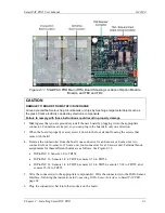
Figure 2-13. ProCamPAC Boards (8- and 16-Channel): Location of Components
6.
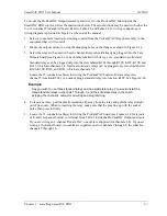
Remove the appropriate connector(s) from its socket on the ProCamPAC board (TB401 for an 8-
channel ProCamPAC, TB451 and TB452 for a 16-channel ProCamPAC). Connect wires from the
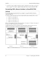
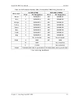
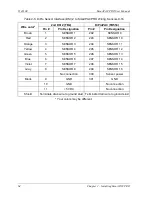
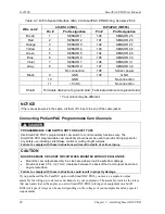
12-conductor cable(s) to the pin locations on the appropriate terminal blocks, as shown in Table
2-8 (for the 8-channel option) or Table 2-8 and Table 2-9 (for the 16-channel option). See also
wiring diagram Figure 3 at the end of the manual.
Summary of Contents for SmartPAC PRO
Page 1: ......
Page 2: ......
Page 4: ......
Page 6: ......
Page 20: ......
Page 22: ......
Page 24: ......
Page 42: ...1143100 SmartPAC PRO User Manual 42 Chapter 1 Introduction to SmartPAC PRO ...
Page 142: ...1143100 SmartPAC PRO User Manual 142 Chapter 4 SmartPAC PRO Program Mode ...
Page 200: ...1143100 SmartPAC PRO User Manual 200 Chapter 6 Using DiProPAC Die Protection Optional ...
Page 222: ...1143100 SmartPAC PRO User Manual 222 Chapter 7 ProCamPAC Instructions ...
Page 254: ...1143100 SmartPAC PRO User Manual Appendix C SmartView Remote Viewing and E mail Setup 254 ...
Page 280: ...SmartPAC PRO User Manual 1143100 280 Appendix C Reporting Downtime and Scrap to SFC ...
Page 290: ...SmartPAC PRO User Manual 1143100 290 Index Y yellow fault 232 yellow sensor 169 ...
Page 292: ......
Page 294: ......
Page 296: ......
Page 298: ......
Page 300: ......
Page 301: ......
Page 302: ......
Page 303: ......
Page 304: ......
Page 305: ......
Page 306: ......
Page 307: ......
Page 308: ......
Page 309: ......
Page 310: ......
Page 311: ......
Page 312: ......
Page 313: ......
Page 314: ......
Page 315: ......
Page 316: ......
Page 317: ......
Page 318: ......

