background image


Antenna Systems


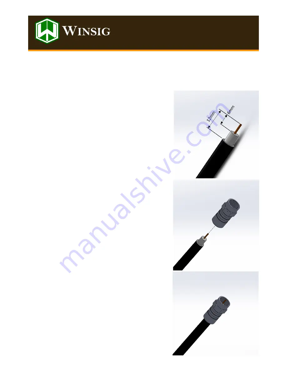
Winsig 3.1 Connector to coaxial cable installation


4.


Once the cable has been prepared, slip the provided push

-

on connector 

over the cable.  The cable must be installed as far as it will go, such that 
the centre copper conductor protrudes from the end of the connector 
by a few millimetres.


5.


Pull backward on the connector to ensure that the small tines have en-
gaged, and you connector is firmly in place.


Note:  The provided connector is suitable for quad shielded RG6 coaxial ca-
ble.  If the retainer tines on the connector have not engaged, your van may 
have a smaller diameter (dual shielded) cable installed.  As every van instal-
lation is different, we do not provide multiple connectors in each kit, howev-
er these connectors can be obtained by contacting us. 


1.


Strip outer plastic cover 12mm from end of cable.


2.


Trim away all steel braid and aluminium foil until white plastic insulator 
is exposed.  Some cable has two layers of this braid and foil.  All must be 
removed. 


3.


Remove 6mm of inner insulation, whilst being careful no to nick the cen-
tre copper conductor.


Note:  a cable stripper designed specifically for coaxial cables will achieve a 
neat and easy result if you have one, but this process can be achieved with a 
sharp utility knife if care is taken.


Before commencing the preparation of your cable, slip the rubber protector boot onto the cable, and slide it out of the way to 
allow easy access to the end to be terminated.


Summary of Contents for 3.1 Ultra Plus Retrofit

Page 1: ...he coaxial cable from inside the antenna boom Note do not disturb the coaxial cable at the roof mounting position This could lead to a leak in the roof of the van 4 Using a pair of needle nosed pliers...

Page 2: ...ect hole for the upper pin is marked LH or RH on the antenna mounting bracket The correct lower hole is diagonally opposite as shown below 8 Now install the vertical plane antenna onto the top tube Sl...

Page 3: ...to the mounting boom This will be achieved by removing the adhesive paper from the underside of the booster and attaching it midway between the cable tie retainers Note It is very important not to be...

Page 4: ...rovided cable tie 16 The coaxial cables for both the Television antenna and the broadband antenna may now be retained with the provided cable ties as show in the figure below right In each case the ca...

Page 5: ...As every van instal lation is different we do not provide multiple connectors in each kit howev er these connectors can be obtained by contacting us 1 Strip outer plastic cover 12mm from end of cable...

Page 6: ...Antenna Systems Winsig 3 1 Ultra Retrofit alternate configurations Winsig 3 1 Ultra Retrofit Left Hand Installation Winsig 3 1 Ultra Retrofit Hybrid Installation...

Page 7: ......

Page 8: ......

Page 9: ...ertical antenna 1 In line amplifier 1 Mounting booms inc bump stop and cable tie retainers 2 F type RG6 coaxial cable connector 1 RF connector boot Black 1 Clevis pins 4 Clevis retaining clips 4 10G x...

Reviews: