WR-G35DDCi Multichannel Coherent Application Guide for Extended topology configuration (ETC)
14
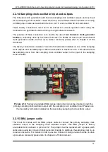
2.2.14 Sampling clock oscillator input and outputs
The Coherent clock generator board has two sampling clock oscillator outputs and one input
for the sampling clock oscillator. These are factory connected as shown in Picture 2-12 using
an SMA jumper cable as described in Section 2.2.15, and one SMA 50 ohm terminator.
These factory connections need not to be altered for normal operation when using the
Coherent clock generator board to drive up to eight coherent receivers.
The purpose of these connectors is to enable the use of
two Coherent clock generator
boards
to coherently drive up to sixteen receivers. For details on how to use two Coherent
clock generator boards (to drive up to sixteen receivers) please refer to chapter 4 of this
document.
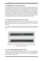
The factory connections consists of one 50 ohm terminator installed on one of the sampling
clock outputs and an SMA jumper cable as described in Section 2.2.15. This interconnects
the sampling clock, from the sampling clock oscillator output to the input of the sampling
clock oscillator.
Picture 2-12:
Factory pre-installed SMA jumper cable interconnecting (marked in red) the
primary sampling clock oscillator output with the sampling clock oscillator input. Please note
the mandatory terminator installed on the secondary sampling clock oscillator output.
2.2.15 SMA jumper cable
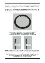
The Clock Kit comes with an SMA jumper cable to connect the primary sampling clock
oscillator output to the sampling clock oscillator output. This SMA jumper is factory
pre-installed and is shown in picture 2-12. The jumper must be replaced with a proper patch
cable when using two Coherent clock generator boards, to distribute the sampling clock to up
to sixteen receivers. For details on how to use two Coherent clock generator boards (to drive
up to sixteen receivers) please refer to chapter 4 of this document.

