Winmate R19L100-MLM1 User Manual Download Page 10


10 

19" G-WIN Military Display User Guide 

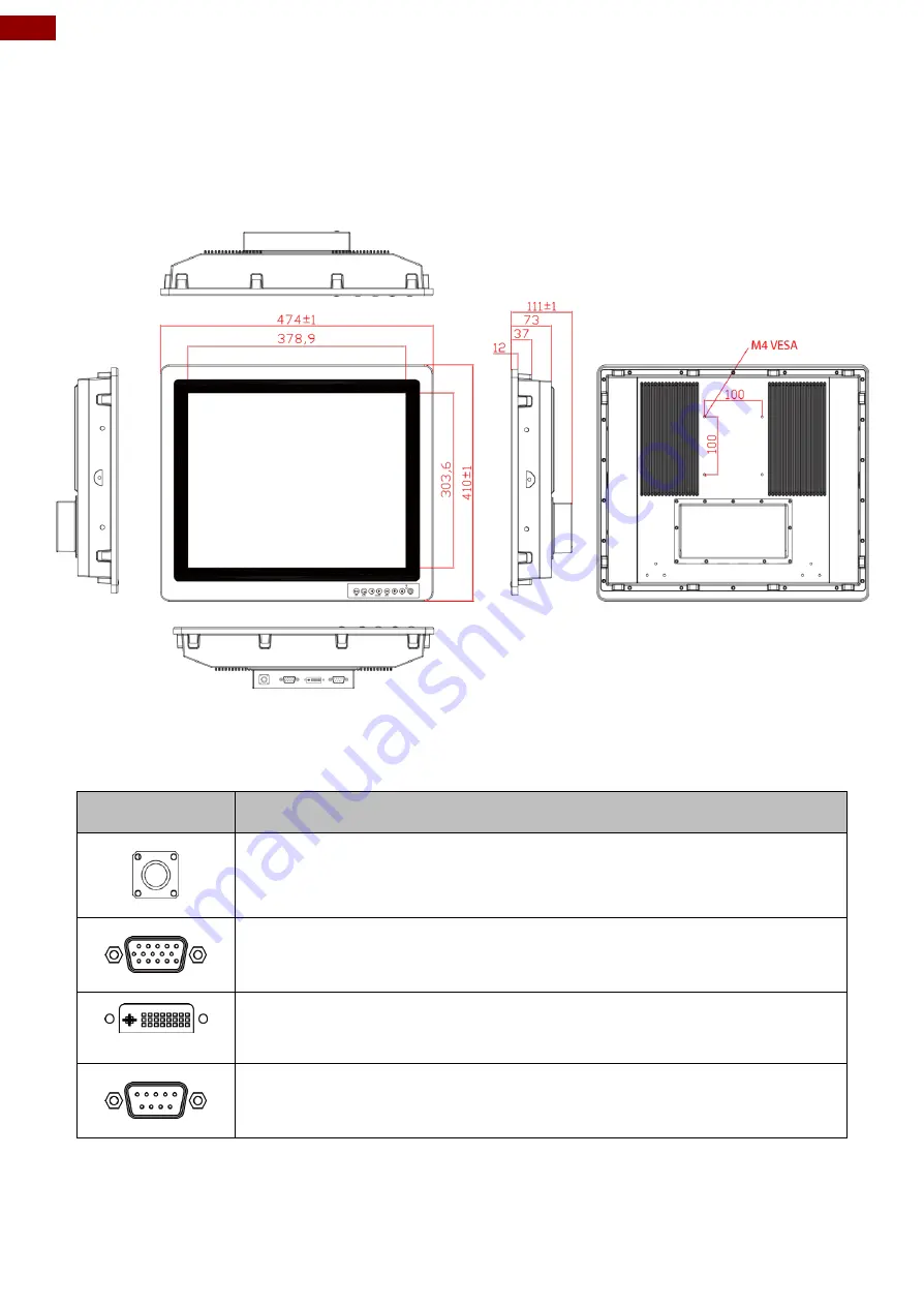
1.4 Product Overview 

This section describes physical appearance of the G-WIN Military Display.


All dimensions shown in mm. 

R19L100-MLM1


1.5 External Connectors 

Terminal interfaces are located on the rear bottom side of the display. 

Item 

Description 


Power Input

 - Military grade lockable power connector (MS27467T9F98S). 

Example: DC power supply.


VGA - 

Transmits video from a PC to a monitor. 

Example: A notebook PC to a monitor.


DVI-D

 - Transmits video from a PC to a monitor. 

Example: A notebook PC to a monitor.


RS232 for Touch

 - Connects touch interface to the monitor. 

Example: A touch to a monitor.


Summary of Contents for R19L100-MLM1

Page 1: ...Please read this instructions before operating the device and retain them for future reference 19 G WIN Military Display R19L100 MLM1 User Manual Version 1 0 Document Part Number 91521110103A ...

Page 2: ...nting Guide 15 2 3 1 Wall Mount 15 2 3 2 VESA Mount 16 2 4 Connecting Peripherals 16 2 5 Connector Description 18 2 5 1 VGA Connector 18 2 5 2 DVI D Connector 19 2 5 3 RS 232 for Remote Control 19 Chapter 3 Operating the Device 20 3 1 Turning On Off the System 21 3 2 Troubleshooting Guide 21 3 3 On Screen Display Menu Navigation 22 3 4 PIP Mode Selection Guide 23 Appendix 24 Appendix A Hardware Sp...

Page 3: ... from the invoice date If the customer discovers a defect we will at his her option repair or replace the defective product at no charge to the customer provide it is returned during the warranty period of one year with transportation charges prepaid The returned product must be properly packaged in its original packaging to obtain warranty service If the serial number and the product shipping dat...

Page 4: ...mage to hardware and explains how to avoid the potential problem Unealerted attention indique un dommage possible à l équipement et explique comment éviter le problem potentiel Warning Avertissement An Electrical Shock Warning indicates the potential harm from electrical hazards and how to avoid the potential problem Un Avertissement de Choc Électriqueindique le potentiel de chocssur des emplaceme...

Page 5: ...enté devrait ouvrir ces chassis Caution Attention Always ground yourself to remove any static charge before touching the CPU card Modern electronic devices are very sensitive to static electric charges As a safety precaution use a grounding wrist strap at all times Place all electronic components in a static dissipative surface or static shielded bag when they are not in the chassis Toujours verif...

Page 6: ...s Before connecting the equipment to the power outlet make sure the voltage of the power source is correct Position the power cord so that people cannot step on it Do not place anything over the power cord If the equipment is not used for a long time disconnect it from the power source to avoid damage by transient over voltage Never pour any liquid into an opening This could cause fire or electric...

Page 7: ...on for specific user needs and includes G WIN Military Display User Manual contains detailed description on how to use the display its components and features Models Size Model Name 19 R19L100 MLM1 Note Some pictures in this manual are samples and can differ from actual product Document Revision History Version Date Note 1 0 19 Nov 2018 New document release ...

Page 8: ...r 1 Introduction This chapter gives you product overview describes features and hardware specification You will find all accessories that come with the display device in the packing list Mechanical dimensions and drawings included in this chapter ...

Page 9: ...housing design Fanless streamlined enclosure for highly efficient heat dissipation Compliant MIL STD 810F G MIL STD 461E F Front control membrane keys 40 to 70 C wide operating temperature with built in intelligent heater 1 3 Package Overview Carefully remove the box and unpack your display Please check if all the items listed below are inside your package If any of these items are missing or dama...

Page 10: ...nterfaces are located on the rear bottom side of the display Item Description Power Input Military grade lockable power connector MS27467T9F98S Example DC power supply VGA Transmits video from a PC to a monitor Example A notebook PC to a monitor DVI D Transmits video from a PC to a monitor Example A notebook PC to a monitor RS232 for Touch Connects touch interface to the monitor Example A touch to...

Page 11: ... disabled it cycles through the available input sources for the Main Display ii When OSD is enabled it moves right when navigating the Main Menu and Sub Menu and increments a slider bar MENU Menu i When OSD is disabled it displays the OSD Main Menu ii When OSD is enabled it confirms a selection Down Selects the next item in the Item Menu Up Selects the previous item in the Item Menu Power Initiate...

Page 12: ...itary Display User Guide Chapter 2 Installation This chapter provides hardware installation instructions and mounting guide for all available mounting options Pay attention to cautions and warning to avoid any damages ...

Page 13: ...ndé le matériel de montage pour éviter le risque de blessure 2 2 Connecting the Power Safety Precautions Do not use the adapter in a high moisture environment Never touch the adapter with wet hands or foot Allow adequate ventilation around adapter while using Do not cover the adapter with paper or other objects that will reduce cooling Do not use the adapter while it is inside a carrying case Do n...

Page 14: ...possible if unit is wired incorrectly or connected to voltage exceeding the input voltage range Des blessures graves en raison du choc est possible si l unité est mal câblé ou connecté à la tension maximale de la plage de tension d entrée Warning Avertissement Make sure that the polarization of the power lines is correct and complete including earth ground Assurez vous que la polarisation des lign...

Page 15: ...e 19 G WIN Military Display supports wall mount and compatible with VESA mount solution Follow the instruction below to complete mounting 2 3 1 Wall Mount Follow instructions below to mount 19 G WIN Military Display into the wall Mounting Steps ...

Page 16: ...ation is complete plug the power cord into a grounded AC outlet Turn on the power Notice that VESA stand and mounting kit are not provided by Winmate 2 4 Connecting Peripherals This Display comes with VGA and DVI interface located on the bottom panel For a nice look and safe installation make sure cables are neatly hidden behind the device Caution Attention Observe all local installation requireme...

Page 17: ...low 1 Turn off your computer and unplug external computer s power cable 2 Connect a VGA DVI cable from your external PC to the VGA DVI port on the display 3 Connect the power cable to the display and the other side to power adapter 4 Plug the power adapter into an electrical outlet 5 Turn on external computer and display Connecting display to external PC via VGA Note For the optimal results select...

Page 18: ...ave to make adjustments to the monitor settings from the OSD menu when switching between these sources 2 5 1 VGA Connector Plug 15 pin VGA signal cable to the VGA connector in the rear of PC system and plug the other end to the monitor Secure cable connectors with screws Pin Assignment and signal names for VGA connector Pin Signal Name Pin Signal Name 1 RED 2 GREEN 3 BLUE 4 NC 5 GND 6 AGND 7 AGND ...

Page 19: ...ntrol is an optional connector and may not be present in your device Use RS 232 D Sub 9pin terminal for remote control RS 232 D Sub 9pin Connector Pin Assignment and Signal Names Pin Signal Name Pin Signal Name 1 DVI_RX2 2 DVI_RX2 3 GND 4 4 5 4 6 DVI SCL 7 DVI SDA 8 NC 9 DVI_RX1 10 DVI_RX1 11 GND 12 3 13 3 14 5V 15 DVI_CON_CABLE 16 DVI_CON_HP 17 DVI_RX0 18 DVI_RX0 19 GND 20 5 21 5 22 GND 23 DVI_CL...

Page 20: ...20 19 G WIN Military Display User Guide Chapter 3 Operating the Device In this chapter you will find instructions on how to operate the display ...

Page 21: ...nchronized Check if the signal cable is firmly seated in the socket Check if the output level matches the input level of your computer Make sure the signal timings of the computer system are within the specification of the monitor The position of the screen is not in the center Adjust the H position and V position or Perform the Auto adjustment The screen is too bright too dark Check if the bright...

Page 22: ... only AUTO ADJUSTMENT ON OFF H Position V Position and Clock Phase are adjusted automatically upon power on VGA only H POSITION slider bar Controls the horizontal position of the image within the Display area of the LCD Press to move right Press to move left VGA only V POSITION slider bar Controls the vertical position of the image within the Display area of the LCD Press to move up Press to move ...

Page 23: ...on PIP Resolution Show BIOS version resolution info OSD RESET YES NO Resets the following settings within the OSD menu back to factory setting ADVANCED CHANNEL SELECT VGA DVI Select the input signal source FLIP OFF H FLIP V FLIP HV FLIP Adjust the flip settings BRIGHTNESS MIN Slider bar ADVANCED RESET YES NO Resets the following settings within the ADVANCED menu back to factory setting FACTORY RES...

Page 24: ...24 19 G WIN Military Display User Guide Appendix This chapter contains additional product information including troubleshooting guide and frequency table ...

Page 25: ...er Input 9 36V DC Mechanical Specifications Dimensions 474 x 410 x 143 5 mm Mounting Rack mount Physical Buttons Power On Off Menu Auto Brightness up Brightness down LED adjustment LED Indicators Power Sleep Weight 10 2 kg Gross 9 0 kg Net Environment Considerations Operating Temp 40 C 70 C with intelligent heater control design Operating Humidity 5 to 95 IP Rating Front IP67 Vibration MIL STD 810...

Page 26: ...tion Refer to the table below for more information about available input signals Signal name Vertical Frequency Hz DVI VGA 640 x 480 60 72 75 480P 60 72 75 800 x 600 60 72 75 1024 x 768 60 72 75 720P 60 72 75 1280 x 1024 60 72 75 1600 x 1200 60 72 75 1920 x 1080 60 72 75 1920 x 1200 60 2560 x 1440 60 3840 x 2160 30 60 4096 x 2160 60 ...

Page 27: ...8GHz 2MHz 18G Hz 44 89 dB Military Grade Environmental Compliance Environmental MIL STD 810F G Compliance High Temperature Operating 30 C to 60 C Method 501 5 Procedure II Storage 30 C to 60 C Method 501 5 Procedure I Low Temperature Operating 33 C Method 502 5 Procedure II Storage 33 C Method 502 5 Procedure I Thermal Shock 33 C to 63 C Method 503 5 Procedure I B Humidity 30 C to 60 C 95 2 RH Met...

Page 28: ... GAMMA OFF 1 GAMMA 1 8 2 GAMMA 2 2 0x8A Gamma 0 0x89 Gamma 1 0x88 Gamma 2 8 Color Temp 0x05 0x40 0x32 0 user 1 9300K 2 6500K 0x89 User 0x88 9300K 0x87 6500K 9 Color R 0x05 0x40 0x33 0x00 0x64 0x88 00 0x24 100 10 Color G 0x05 0x40 0x34 0x00 0x64 0x87 00 0x23 100 11 Color B 0x05 0x40 0x35 0x00 0x64 0x86 00 0x22 100 12 Hue 0x05 0x40 0x12 0x00 0x64 0xA9 00 0x45 100 13 Saturation 0x05 0x40 0x13 0x00 0x...

Page 29: ...K 2 6500K 0xCA user 0xC9 9300k 0xC8 6500k Color R 0x04 0x30 0x33 0x99 0x04 0x33 0x00 0x64 0xC9 0 0x65 100 Color G 0x04 0x30 0x34 0x98 0x04 0x34 0x00 0x64 0xC8 0 0x64 100 Color B 0x04 0x30 0x35 0x97 0x04 0x35 0x00 0x64 0xC7 0 0x63 100 Hue 0x04 0x30 0x12 0xBA 0x04 0x12 0x00 0x64 0xEA 0 0x86 100 Saturation 0x04 0x30 0x13 0xB9 0x04 0x13 0x00 0x64 0xE9 0 0x85 100 InterBright 0x04 0x30 0x14 0xB8 0x04 0x...

Page 30: ...n permanent staining or discoloration may occur Cleaning the Casing Use the following procedure to clean the equipment Caution Attention Always turn off the device and disconnect other peripherals before cleaning and maintenance procedures Toujours éteindre l appareil et débrancher tous les périphériques avant que les procédures de nettoyage et d entretien Before Cleaning Make sure the device is t...

Page 31: ...________________________________________________________________ ______________________________________________________________________________ ______________________________________________________________________________ ______________________________________________________________________________ ______________________________________________________________________________ ___________________...

Page 32: ...Winmate Inc 9F No 111 6 Shing De Rd San Chung District New Taipei City 24158 Taiwan R O C www winmate com Copyright Winmate Inc All rights reserved ...

Reviews: