background image


20 

15~23.8" P-Cap Open Frame Panel PC (IK70) Quick Start Guide 

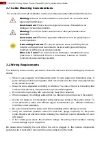
3.1 Cable Mounting Considerations 

For a nice look and safe installation, make sure cables are neatly hidden behind the device.  


Warning! 

Observe all local installation requirements for connection cable 

type and protection level.


Avertissement ! 

Suivre tous les règlements locaux 

d’installations, de 

câblage et niveaux de protection. 


Warning! 

Turn off the device and disconnect other peripherals before 

installation. 


Avertissement ! 

Éteindre l’appareil et débrancher tous les périphériques 

avant l’installation. 


3.2 Wiring Requirements


The following common safety precautions should be observed before installing any electronic 
device:  

  Strive  to  use  separate,  non-intersecting  paths  to  route  power  and  networking  wires.  If 

power wiring and device wiring paths must cross make sure the wires are perpendicular 
at the intersection point.  

  Keep  the  wires  separated  according  to  interface.  The  rule  of  thumb  is  that  wiring  that 

shares similar electrical characteristics may be bundled together.  

  Do not bundle input wiring with output wiring. Keep them separate.  

  When necessary, it is strongly advised that you label wiring to all devices in the system. 

  Do  not  run  signal  or  communication  wiring  and  power  wiring  in  the  same  conduit.  To 

avoid  interference,  wires  with  different  signal  characteristics  (i.e.,  different  interfaces) 
should be routed separately.  

  Be sure to disconnect the power cord before installing and/or wiring your device.  

  Verify  the  maximum  possible  current  for  each  wire  gauge,  especially  for  the  power 

cords.  Observe  all  electrical  codes  dictating  the  maximum  current  allowable  for  each 
wire gauge.  

  If  the  current  goes  above  the  maximum  ratings,  the  wiring  could  overheat,  causing 

serious damage to your equipment.  

Be  careful  when  handling  the  unit.  When  the  unit  is  plugged  in,  the  internal  components 
generate a lot of heat which may leave the outer casing too hot to touch. 


Alternating Currrent ! 

To prevent electrical shock, the Safety Ground  

location on the rear must be bonded to the local earth ground through a 
minimum 12 AWG wire as short as possible


Mise à le Terre! 

Pour éviter les chocs électriques, l

’emplacement de la 

prise terre  à  

l’arrière doit  être lié  à  terre locale,  à travers un 12 AWG 

minimum et aussi court que possible. 

Summary of Contents for R15IK7T-POC3

Page 1: ...P Cap Open Frame Panel PC Intel Core i7 7700T 2 9 GHz Intel Core i5 7500T 2 7 GHz Intel Core i3 7100T 3 4 GHz Incredible system expandability for versatile applications Model No R15IK7T POC3 R17IK7T...

Page 2: ...7 2 2 VESA Mount 18 Chapter 3 Getting Started 19 3 1 Cable Mounting Considerations 20 3 2 Wiring Requirements 20 3 3 Connecting Power 21 3 4 Connecting to Other Devices 22 3 4 1 Power Input Connector...

Page 3: ...f the customer discovers a defect we will at his her option repair or replace the defective product at no charge to the customer provide it is returned during the warranty period of one year with tran...

Page 4: ...vertissement Un Avertissement de Choc lectriqueindique le potentiel de chocssur des emplacements lectriques et comment viterces probl mes Safety Information Warning Always completely disconnect the po...

Page 5: ...stallation Dropping it or letting it fall could cause damage The openings on the enclosure are for air convection and to protect the equipment from overheating Before connecting the equipment to the p...

Page 6: ...tion for specific user needs and includes IK70 SBC User Manual contains detailed description on how to use the panel PC running on IK70 SBC contains BIOS setting and driver installation procedure Quic...

Page 7: ...ntroduction This chapter gives you product overview describes features and hardware specification You will find all accessories that come with the panel PC in the packing list Mechanical dimensions an...

Page 8: ...I port 1 2 Product Features Winmate P Cap Open Frame Panel PC features 15 17 19 21 5 and 23 8 TFT LCD Intel 7th Generation Core i3 i5 i7 Kaby Lake processor Slim line design in open frame housing Mult...

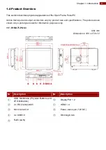
Page 9: ...vary by product size and specifications The picture above shows only a prototype model for information purposes only 15 R15IK7T POC3 Unit mm Dimensions 360 x 272 x 72 Description Description OSD Membr...

Page 10: ...art Guide 17 R17IK7T POM1 Unit mm Dimensions 407 x 338 x 78 Description Description OSD Membrane Physical Buttons and LED Indicators DisplayPort 1 2 2 x RS 232 422 485 HDMI 1 4 Mic In Line Out Power J...

Page 11: ...K7T POM1 Unit mm Dimensions 457 x 382 x 71 Description Description OSD Membrane Physical Buttons and LED Indicators DisplayPort 1 2 2 x RS 232 422 485 HDMI 1 4 Mic In Line Out Power Jack 4 pin 12V DC...

Page 12: ...rt Guide 21 5 W22IK7T POA3 Unit mm Dimensions 525 x 316 x 72 Description Description OSD Membrane Physical Buttons and LED Indicators DisplayPort 1 2 2 x RS 232 422 485 HDMI 1 4 Mic In Line Out Power...

Page 13: ...IK7T POA2 Unit mm Dimensions 615 x 385 x 75 Description Description OSD Membrane Physical Buttons and LED Indicators DisplayPort 1 2 2 x RS 232 422 485 HDMI 1 4 Mic In Line Out Power Jack 4 pin 12V DC...

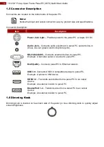
Page 14: ...ut green and microphone pink RS 232 422 485 Connects external devices to panel PC Example A barcode reader or scanner to panel PC RJ45 LAN Connects panel PC to Ethernet network USB 3 0 Connects USB 3...

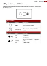
Page 15: ...embrane on the rear bottom side of the panel PC Physical Buttons Icon Button Description Reset Press to reset the system Power On Off Press to power on or power off the device LED Indicators LED Type...

Page 16: ...23 8 P Cap Open Frame Panel PC IK70 Quick Start Guide Chapter 2 Mounting This chapter provides mounting guide for all available mounting options Pay attention to cautions and warning to avoid any dam...

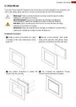
Page 17: ...le risque de blessure Caution Follow mounting instructions and use recommended mounting hardware to avoid the risk of injury Attention Suivez les instructions de montage et d utilisation recommand le...

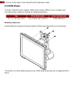
Page 18: ...ution suitable for all kinds of industrial applications Size VESA Dimensions Screw Hole Diameter 15 17 19 21 5 23 8 75 x 75 mm 100 x 100 mm 8 M4 VESA D 3 Mounting Instruction Use M4 VESA D 3 screws to...

Page 19: ...19 Chapter 3 Getting Started Chapter 3 Getting Started This chapter tells you important information on power supply adapter and precautions tips Pay attention to power considerations...

Page 20: ...Do not bundle input wiring with output wiring Keep them separate When necessary it is strongly advised that you label wiring to all devices in the system Do not run signal or communication wiring and...

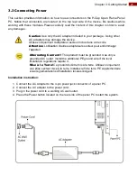
Page 21: ...utilisation d autres adaptateurs secteur peut endommager l appareil Installation instruction 1 Connect the AC Adapter to the 4 pin power jack connector of a panel PC 2 Connect the AC adapter to the p...

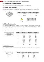
Page 22: ...can configure serial port RS 232 422 485 settings in BIOS Please refer to Ik70 SBC User Manual for more details Pin assignment and connector description of serial port connector 3 4 3 RJ 45 Connector...

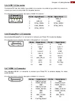
Page 23: ...connector to connect your Panel PC to external display for video audio transfer Pin assignment and connector description of HDMI 1 4 connector Pin Signal Name Pin Signal Name 1 5V 2 USB_D 3 USB_D 4 GN...

Page 24: ...Start Guide 3 4 8 Audio Connector Your panel PC has two stereo audio ports with phone jack connectors one is Line out and the other one is Mic in Pin assignment and connector description of audio jack...

Page 25: ...25 Chapter 4 Operating the Device Chapter 4 Operating the Device In this chapter you will find instructions on how to operate the panel PC...

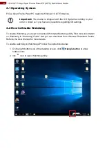
Page 26: ...regarding OS settings 4 2 How to Enable Watchdog To enable Watchdog you need to download Winmate Watchdog utility Find more information on Watchdog in Watchdog Guide that you can download from Winmat...

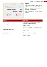
Page 27: ...countdown time reaches 0 Every 9 min watchdog timer will be reset to 10 min Setting Description Watchdog Countdown Time The system automaticity restarts when this countdown time reaches zero Default...

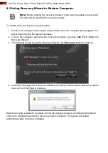
Page 28: ...power source during the recovery process 2 Turn on the computer and when the boot screen shows up press Tab F6 to initiate the Recovery Wizard 3 The following screen shows the Recovery Wizard Click Re...

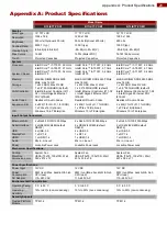
Page 29: ...abit Ethernet PHY I219 LM Audio Codec Realtek HD Audio Codec Realtek HD Audio Codec Realtek HD Audio Codec Expansion Slot 2 x M 2 1 for Wi Fi 1 for SSD 1 x PCIe x16 Optional 2 x M 2 1 for Wi Fi 1 for...

Page 30: ...it Ethernet PHY I219 LM Audio Codec Realtek HD Audio Codec Realtek HD Audio Codec Expansion Slot 2 x M 2 1 for Wi Fi 1 for SSD 1 x PCIe x16 Optional 2 x M 2 1 for Wi Fi 1 for SSD 1 x PCIe x 16 Optiona...

Page 31: ..._______________________ ______________________________________________________________________________ ______________________________________________________________________________ __________________...

Page 32: ...Winmate Inc 9F No 111 6 Shing De Rd San Chung District New Taipei City 24158 Taiwan R O C www winmate com Copyright Winmate Inc All rights reserved...

Reviews: