

QUICK START GUIDE
MXT-700
7" Modero X® Series Tabletop Touch Panel
Overview
The MXT-700 7" Modero X Series
®
Tabletop Touch Panel (
FG5968-04
) features
edge-to-edge capacitive touch glass with multi-touch capabilities, as well as
advanced technology empowering users to operate AV equipment seamlessly,
while providing the ultimate in audio and video quality. The distinctive appearance
will complement even the most sophisticated meeting facilities and homes.
Product Specifications
Note: The MXT-700-NC (FG5968-27) No Comm touch panel does not have
microphone capability. It otherwise has all of the functionality of the MXT-700
panel.
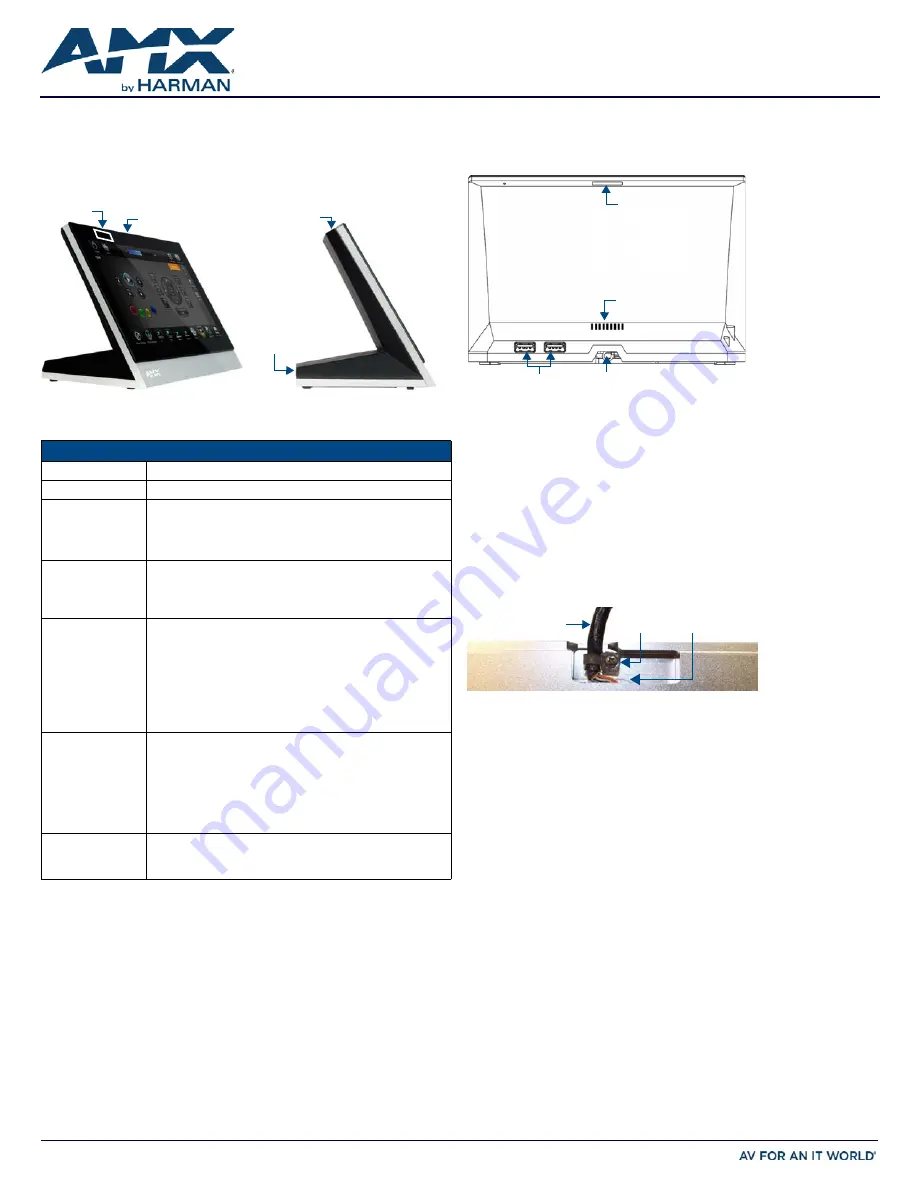
Connector Locations
USB peripherals (mouse, keyboard, etc.) may be connected to either of the two
USB ports on the rear of the device. Updates to the device’s firmware can also
made via the USB ports (FIG. 2).
Power via PoE
Power for the MXT-700 is supplied via PoE (Power Over Ethernet ), utilizing an
AMX-certified, capacitive touch-compliant PoE injector such as the PS-POE-AT
High Power PoE Injector (
FG423-81
) or other approved AMX PoE power source
Connect the incoming Ethernet cable to the RJ45 port on the cable attached to
the device.
Ethernet Cable Installation and Modification
In installations where you wish to conceal the Ethernet cable, a hole at least 1.00”
(2.54 cm) in diameter is required in the surface to allow passage of the female
RJ45 connector (FIG. 3).
If using a smaller hole is unavoidable, you will need to disconnect the Ethernet
cable (
ECA5968-05
) from the device, to feed the male end of the cable through.
Note: The minimum diameter hole through which the Ethernet cable may pass is
0.50" (1.27 cm).
To disconnect and reconnect the MXT-700’s Ethernet cable:
1.
On a soft surface, turn the MXT-700 face-down to access the bottom of the
device.
2.
Remove the clamp holding the Ethernet cable (FIG. 3).
3.
Remove the Ethernet cable connector and pull the cable out of the clamp.
4.
Pass the Ethernet cable (
ECA5968-05
) through the hole, with the RJ45
connector on the other side of the installation surface from the device.
5.
Press the Ethernet cable back into the clamp.
Do
NOT
tighten the clamp at this time.
6.
Using a non-conductive item such as a wooden stick, reinsert the Ethernet
cable connector into the device. Ensure that the connector is properly
seated.
7.
Tighten the clamp to secure the Ethernet cable.
Make sure the clamp is around the bundled black cable, not the individual
wires.
8.
Connect the RJ45 connector to its incoming Ethernet cable and apply power.
FIG. 1
MXT-700
MXT-700 SPECIFICATIONS
Dimensions (HWD)
5" x 7 5/16" x 4 1/8" (126 mm x 187 mm x 105 mm)
Weight
1.8 lbs (0.82 Kg)
Power Consumption • Full-On: 8W
• Standby: 3.2W
• Shutdown: 1W
• Start-Up Inrush Current: Not applicable due to PoE standard
External Power
Supply Required
Optimal performance requires use of one of the following AMX
PoE power supplies (not included):
• PS-POE-AF-TC, PoE Injector, 802.3AF Compliant (FG423-83)
• NXA-ENET8-2POE, Gigabit PoE Ethernet Switch (FG2178-63)
Certifications
• UL 60950-1
• FCC Part 15 Class B
• C-Tick CISPR 22 Class B
• CE EN 55022, EN 55024 and EN 60950-1
• IEC 60950-1
• IC
• IEC/EN-60950
• RoHS/WEEE compliant
Environmental
• Temperature (Operating): 32°F to 104°F (0°C to 40°C)
• Temperature (Storage): 4°F to 140°F (-20°C to 60°C)
• Humidity (Operating): 20% to 85% RH
• Humidity (Storage): 5% to 85% RH
• Power ("Heat") Dissipation:
On: 18.5 BTU/hr
Standby: 10.6 BTU/hr
Included
Accessories
• MXA-USB-C, USB Port Cover Kit (
FG5968-18
)
• 3/4" Mini-Grommet (
FG570-01
)
• MXA-CLK, Modero X/S Series Cleaning Kit (
FG5968-16
)
Sleep Button
NFC Sensor
Sleep Button
USB Ports (2)
FIG. 2
MXT-700 - REAR VIEW
FIG. 3
BOTTOM OF THE MXT-700
USB Ports Entry for RJ45/PoE Cable
Speaker
Sleep button
Ethernet Cable
Connector
Clamp