


User Manual
Chapter 4
AMI
UEFI BIOS Setup
42
IP65 Stainless Resistive Panel PC
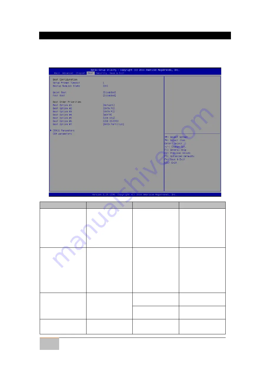
4.2.3 Boot Menu
The Boot menu sets the sequence of the devices to be searched for the operating
system. The bootable devices will be automatically detected during POST and shown
here, allowing you to set the sequence that the BIOS use to look for a boot device from
which to load the operating system.
BIOS Setting
Description
Setting Option
Effect
Setup Prompt
Timeout
Allows user to
configure the
number of seconds
to stay in BIOS
setup prompt
screen.
Enter
Set the prompt
timeout
Boot NumLock
State
Enables or disables
NumLock feature
on the numeric
keypad of the
keyboard after the
POST (Default:
On).
On/ Off
Remains On or OFF
Quite Boot
Determines if POST
message or OEM
logo is displayed.
Disabled
Disables this
function
Enabled
Enables this
function
Fast Boot
Enables or disables
Fast Boot to
Disabled
Disables this
function


