background image


- 3 - 

FCC Statement  


This device complies with part 15 FCC rules.  
Operation is subject to the following two conditions: 


This device may not cause harmful interference. 


This device must accept any interference received 
including interference that may cause undesired 
operation. 
 

This equipment has been tested and found to comply with the limits for a 
class "B" digital device, pursuant to part 15 of the FCC rules. These limits are 
designed to provide reasonable protection against harmful interference when 
the equipment is operated in a commercial environment. This equipment 
generates, uses, and can radiate radio frequency energy and, if not installed 
and used in accordance with the instruction manual, may cause harmful 
interference to radio communications. Operation of this equipment in a 
residential area is likely to cause harmful interference in which case the user 
will be required to correct the interference at him own expense. 

European Union 


Electromagnetic Compatibility Directive (2014/30/EU) 


  EN55024: 2010/ A1: 2015 

o

  IEC61000-4-2: 2009  

o

  IEC61000-4-3: 2006+A1: 2007+A2: 2010 

o

  IEC61000-4-4: 2012  

o

  IEC61000-4-5: 2014  

o

  IEC61000-4-6: 2014 

o

  IEC61000-4-8: 2010 

o

  IEC61000-4-11: 2004 

  EN55032: 2012/AC:2013 

  EN61000-3-2:2014 

  EN61000-3-3:2013 

Low Voltage Directive (2014/35/EU) 


  EN 60950-1:2006/A11:2009/A1:2010/A12:2011/ 

A2:2013 


This  equipment  is  in  conformity  with  the  requirement  of  the  following  EU 
legislations  and  harmonized  standards.  Product  also  complies  with  the 
Council directions. 


Summary of Contents for R10IB3S-GST2

Page 1: ...ture use G WIN Slim IP65 P CAP Panel PC Intel Celeron Bay Trail M N2930 1 83GHz W10IB3S GSH1 R10IB3S GST2 R12IB3S GSM2 HB R15IB3S GSC3 HB Quick Start Guide V1 1 For more information on this and other...

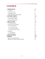
Page 2: ...3 Turning off Your Device 16 3 INSTALLATION 17 3 1 Wiring Requirements 17 3 2 Connecting to Other Devices 18 3 3 Connector Description 19 3 3 1 Power Input Connector 19 3 3 2 Serial Interface Connect...

Page 3: ...talled and used in accordance with the instruction manual may cause harmful interference to radio communications Operation of this equipment in a residential area is likely to cause harmful interferen...

Page 4: ...If the customer discovers a defect we will at his her option repair or replace the defective product at no charge to the customer provide it is returned during the warranty period of one year with tra...

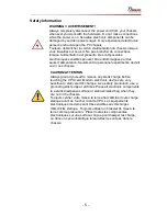
Page 5: ...ent devrait ouvrir ces chassis CAUTION ATTENTION Always ground yourself to remove any static charge before touching the CPU card Modern electronic devices are very sensitive to static electric charges...

Page 6: ...ies Panel PC operates on Intel Celeron Bay Trail M N2930 1 83 GHz processor and supports Windows operating system The Panel PC features Projected Capacitive Multi Touch P CAP These models are full IP...

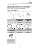
Page 7: ...of these items are missing or damaged contact us immediately Standard factory shipment list Panel PC Quick Start Guide Hardcopy Driver CD User Manual Varies by product specifications 91521110100P 917...

Page 8: ...8 1 3 Description of Parts W10IB3S GSH1 Unit mm Dimensions 263 28 x 173 6 x 40 2 Description Description 9 36V DC M12 Type 1 Watt Speaker LAN USB M12 Type OSD Control Panel RS232 M12 Type...

Page 9: ...9 R10IB3S GST2 Unit mm Dimensions 252 61 x 198 x 36 4 Description Description 9 36V DC M12 Type 1 Watt Speaker LAN USB M12 Type OSD Control Panel RS232 M12 Type...

Page 10: ...10 R12IB3S GSM2 HB Unit mm Dimensions 296 2 x 226 7 x 45 5 Description Description 9 36V DC M12 Type 1 Watt Speaker LAN USB M12 Type OSD Control Panel RS232 M12 Type...

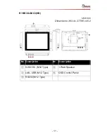
Page 11: ...11 R15IB3S GSC3 HB Unit mm Dimensions 363 4 x 277 86 x 45 2 Description Description 9 36V DC M12 Type 1 Watt Speaker LAN USB M12 Type OSD Control Panel RS232 M12 Type...

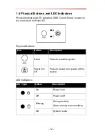
Page 12: ...the rear side of the Panel PC Physical Buttons Icon Button Description Reset Press to reset the system Power On Off Press to power on or power off the device LED Indicators LED Type Status Descriptio...

Page 13: ...he protective cap of the power connector 2 Connect power cable to the connector of your device Make sure the cable fits to the connector then tighten the O ring by turning clockwise to secure the conn...

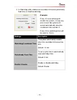
Page 14: ...chdog in Watchdog Guide that you can download from Winmate Download Center or File Share Refer to the User Manual for more details To enable watchdog in Watchdog AP follow the instructions below 1 On...

Page 15: ...l restart automatically when the countdown time reaches 0 Every 9 min watchdog timer will be reset to 10 min Settings Description Watchdog Countdown Time The system automaticity restarts when this cou...

Page 16: ...16 2 3 Turning off Your Device Disconnect the power cord from the Panel PC to completely turn off the device...

Page 17: ...sed that you label wiring to all devices in the system CAUTION Do not run signal or communication wiring and power wiring in the same conduit To avoid interference wires with different signal characte...

Page 18: ...pped with protective caps To ensure the waterproof function can work properly make sure that the protective caps and have been securely tightened whenever the connectors are not used IMPORTANT Please...

Page 19: ...l PC has M12 type 3 pin male power input connector which accepts 9 36 V DC power input Use IP65 power cable to connect the Panel PC to the source of power IMPORTANT If ignition pin IGN_IN is not conne...

Page 20: ...20 3 3 2 Serial Interface Connector Panel PC has M12 type 10 pin male RS 232 connector Use IP65 serial cable to connect the Panel PC to external devices...

Page 21: ...3 3 3 Giga LAN USB 2 0 Connector Panel PC has M12 12 pin male Giga LAN and USB connector that supports two LAN and one USB 2 0 Use IP65 Giga LAN USB 2 0 cable to connect the Panel PC to external devi...

Page 22: ...ptions to fit any industrial use or vehicle Size VESA Plate 10 1 10 4 12 1 75x75 mm 15 100x100 mm Mounting Instruction Use Philips M4x5 screws to fix the desk stand to VESA holes on the back cover of...

Page 23: ...w Hole Diameter mm 10 1 249 x 157 6 M4x5 10 4 227 x 174 5 M4x5 12 1 281 x 206 M4x5 15 345 4 x 260 M6x4 Mounting Instruction 1 Prepare a fixture for the specific dimensions of the device 2 Cut a hole o...

Page 24: ...1 typ 700 1 typ 700 1 typ Viewing Angle 75 80 H 80 80 V 88 88 H 88 88 V 80 80 H 70 70 V 80 80 H 70 70 V Max Colors 16 7M 16 2M 16 2M 16 2M 8bits Touch Projected Capacitive Multi Touch P CAP with opti...

Page 25: ...W 24W 25W Mechanical Specifications Cooling System Fanless Design Mounting VESA Mounting Panel Mounting Environment Considerations Operating Temperature 15 C to 55 C Operating Humidity 10 to 95 non co...

Page 26: ...play area is highly prone to scratching Do not use ketene type material ex Acetone Ethyl alcohol toluene ethyl acid or Methyl chloride to clear the panel It may permanently damage the panel and void t...

Page 27: ...File Type Description 1 SDK Watchdog SDK 2 Utility Watchdog Utility To find the Drivers and SDK please refer to the Driver CD that comes in the package or contact us Also you can download drivers fro...

Page 28: ...Winmate Inc 9F No 111 6 Shing De Rd San Chung District New Taipei City 24158 Taiwan R O C Tel 886 2 8511 0288 Fax 886 2 8511 0211 Email sales winmate com tw Official website www winmate com...

Reviews: