background image


26 

PT-Series Multi-Touch HMI User Manual 

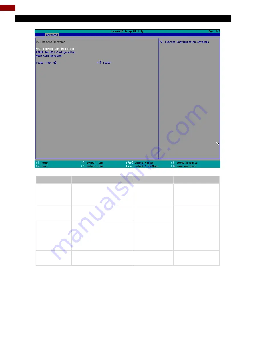
4.2.2.5 PCH-IO Configuration 


BIOS Setting 

Description 

Setting Option 

Effect 

PCI Express 

Configuration 

PCI Express clock gating 

enable/disable for each root 

port. 

Enter 

Opens sub-menu 

SATA And RST 

Configuratuion 

Enable/ Disable SATA device 

Enter 

Opens sub-menu 

USB 

Configuration 

Selectively enable/ disable 

the corresponding USB port 

from reporting a Device 

Connection to the controller. 

Enter 

Opens sub-menu 

State After G3 

System power state setting 

S0 State 

S5 State 


Summary of Contents for PT Series

Page 1: ... before using this product and save this manual for future use PT Series Multi Touch Chassis HMI Intel Core i5 7200U 2 5 GHz turbo to 3 1 GHz Optional Core i7 7500U 2 7 GHz 32 Model No W32IK3S PTA2 User Manual Part No 91521110104Z Version 1 0 ...

Page 2: ...thernet Connector 14 2 4 3 Serial Port Connector 14 2 4 4 USB Connector 15 2 4 5 HDMI Connector 15 2 5 Speaker 16 Chapter 3 Operating the Device 17 3 1 Introduction 17 3 2 Multi Touch 17 3 3 How to Enable Watchdog 18 3 4 Using Recovery Wizard to Restore Computer 18 Chapter 4 Insyde BIOS Setup 20 4 1 How and When to Use BIOS Setup 20 4 2 BIOS Functions 21 4 2 1 Main Menu 21 4 2 2 Advanced 22 4 2 3 ...

Page 3: ...er 53 5 6 Watchdog Driver Installation 56 Chapter 6 Maintenance and Troubleshooting 61 6 1 Cleaning the LCD Monitor 61 6 2 Basic Troubleshooting 61 Appendix 62 Appendix A Product Specifications 62 Appendix B Technical Support 63 ...

Page 4: ...nications Operation of this equipment in a residential area is likely to cause harmful interference in which case the user will be required to correct the interference at him own expense European Union Electromagnetic Compatibility Directive 2014 30 EU EN55024 2010 A1 2015 o IEC61000 4 2 2009 o IEC61000 4 3 2006 A1 2007 A2 2010 o IEC61000 4 4 2012 o IEC61000 4 5 2014 o IEC61000 4 6 2014 o IEC61000...

Page 5: ... be made according to the shipping date In the serial numbers the third and fourth two digits give the year of manufacture and the fifth digit means the month e g with A for October B for November and C for December For example the serial number 1W16Axxxxxxxx means October of year 2016 Customer Service We provide a service guide for any problem by the following steps First visit the website of our...

Page 6: ...ve to static electric charges As a safety precaution use a grounding wrist strap at all times Place all electronic components in a static dissipative surface or static shielded bag when they are not in the chassis Toujours verifier votre mise à la terre afin d éliminer toute charge statique avant de toucher la carte CPU Les équipements électroniques moderns sont très sensibles aux décharges d élec...

Page 7: ...n set for the PT Series HMI provides information for specific user needs and includes User Manual contains detailed description on how to use the Panel PC its components and features Quick Start Guide contains detailed description on how to use the Panel PC its components and features Note Some pictures in this guide are samples and can differ from actual product Document Revision History Version ...

Page 8: ... computing performance with 7th Gen Intel Core i5 7200U Kaby Lake processor Fanless cooling system and ultra low power consumption Front IP65 for protection against water and dust A true flat easy to clean front surface with edge to edge design Plenty of I O including 2 x LAN 1 x COM 2 x USB 3 0 1 x HDMI 1 2 Package Contents Carefully remove the box and unpack your device Please check if all the i...

Page 9: ...a RS 232 422 485 2 x RJ 45 2 x USB 3 0 OSD Control Panel 1 4 Physical Buttons PT Series HMI has five physical buttons located on the bottom side Item Description Power Press to turn on off the device Up Press to adjust volume brightness up Down Press to adjust volume brightness down Left Press to move LEFT in the navigation menu Right Press to move RIGHT in the navigation menu ...

Page 10: ...Description Power Jack Provides power to the panel PC accepts 12V DC power input Optional 9 36V DC HDMI Transmits and protects copyrighted digital video and audio Example An HD tuner to an HD ready TV RS 232 422 485 Connects external devices to HMI device Example A barcode reader or scanner to HMI device USB 2 0 USB 3 0 Connects USB2 0 and USB 3 0 compatible devices to HMI device Example A printer...

Page 11: ...sary it is strongly advised that you label wiring to all devices in the system Do not run signal or communication wiring and power wiring in the same conduit To avoid interference wires with different signal characteristics i e different interfaces should be routed separately Be sure to disconnect the power cord before installing and or wiring your device Verify the maximum possible current for ea...

Page 12: ...of mounting options to fit any industrial use Size VESA Plate Screw Size 32 100x200 mm 200x200 mm M4 x 5 Installation Instruction Use Philips M4x5 screws to fix the desk stand to VESA holes on the back cover of the device The picture is for demonstration purposes only VESA mount accessories are not supplied by Winmate ...

Page 13: ...rd to AC adapter 3 Plug the power cord to the AC outlet 4 Press Power button on the rear OSD panel Caution Use only the AC adapter included in your package Using other AC adapters may damage the device Alternating Current This product must be grounded Use only a grounded AC outlet Install the additional PE ground wire if the local installation regulations require it ...

Page 14: ...nternet Pin assignment and signal names of Ethernet connector 2 4 3 Serial Port Connector Use COM1 serial port connector to connect your HMI to external devices such as mouse modem or printer You can configure serial port settings via BIOS Pin assignment and signal names of serial port connector Pin Name Pin Name 1 DC_IN 2 GND Voltage Minimum Voltage 11 4V Maximum Voltage 12 6V Maximum Current 4 2...

Page 15: ... HDMI1 4a connector Pin assignment and signal name of HDMI connector Pin Name Pin Name 1 5V 2 USB_D 3 USB_D 4 GND 5 STDA_SSRX 6 STDA_SSRX 7 GND_DRAIN 8 STDA_SSTX 9 STDA_SSTX 10 5V 11 USB_D 12 USB_D 13 GND 14 STDA_SSRX 15 STDA_SSRX 16 GND 17 STDA_SSTX 18 STDA_SSTX Pin No Signal Name Pin No Signal Name 1 HDMI_DET 2 NC 3 HDMI_D2P 4 GND 5 HDMI_D2M 6 HDMI_D1P 7 GND 8 HDMI_D1M 9 HDMI_D0P 10 GND 11 HDMI_...

Page 16: ...16 PT Series Multi Touch HMI User Manual 2 5 Speaker Two speakers 5 Watt are located on the rear side of the HMI ...

Page 17: ...r two fingers up and down Selection Drag left to right with one finger Mouse drag Selection Drag one finger left right Zoom Zoom default to CTRL key scroll wheel Move two fingers apart toward each other Rotate No system default unless handled by Application Move two fingers in opposite directions or Use one finger to pivot around another Two Finger tap N A Exposed through Gesture API used by Appli...

Page 18: ...ity 3 In Watchdog utility window set countdown time and periodically feed time or disable watchdog Example Every 10 min watchdog will monitor the system in case any error occurs the system will restart automatically when the countdown time reaches 0 Every 9 min watchdog timer will be reset to 10 min Setting Description Watchdog Countdown Time The system automaticity restarts when this countdown ti...

Page 19: ...ocess 2 Turn on the computer and when the boot screen shows up press Tab F6 to initiate the Recovery Wizard 3 The following screen shows the Recovery Wizard Click Recovery button to continue 4 A warning message about data loss will show up Make sure the data is backed up before recovery and click Yes to continue Wait the recovery process to complete During the recovery process a command prompt wil...

Page 20: ...version of BIOS on the website You may need to run BIOS setup utility for reasons listed below 1 Error message on screen indicates to check BIOS setup 2 Restoring the factory default settings 3 Modifying the specific hardware specifications 4 Necessity to optimize specifications BIOS Navigation Keys The following keys are enabled during POST Key Function Del Enters the BIOS setup menu F7 Display t...

Page 21: ...n is the main menu It contains the system information including BIOS version processor RC version system language time and date BIOS Setting Description Setting Option Effect Language Displays the system language English is set up by default Adjustment of the language Set the language in other language The language in this device is English System Time This is current time setting The time is main...

Page 22: ...ges Caution Handle advanced BIOS settings page with caution Any changes can affect the operation of your computer BIOS Setting Description Setting Option Effect CPU Configuration Configures Trusted Computing parameters Enter Opens submenu Power Performance Configures Power Performance parameters Enter Opens submenu System Agent Configuration Configures System Agent Configuration parameters Enter O...

Page 23: ...re capabilities provided by Vanderpool Technology Active Processor Cores Number of core to enable in each processor package AII 1 2 3 Select number of core to enable in each processor package Hyper Threading Intel Hyper Threading Technology allows a single processor to execute two or more separate threads concurrently Enable Disable Enable or disable Hyper Threading AES Enable or disable AES Advan...

Page 24: ...24 PT Series Multi Touch HMI User Manual 4 2 2 2 F81886A Configuration BMP 4 2 2 3 GPIO Configuration ...

Page 25: ...25 Chapter 4 Insyde BIOS Setup 4 2 2 4 Hardware Monitor ...

Page 26: ...ess clock gating enable disable for each root port Enter Opens sub menu SATA And RST Configuratuion Enable Disable SATA device Enter Opens sub menu USB Configuration Selectively enable disable the corresponding USB port from reporting a Device Connection to the controller Enter Opens sub menu State After G3 System power state setting S0 State S5 State ...

Page 27: ...27 Chapter 4 Insyde BIOS Setup 4 2 2 6 PCI Express Configuration ...

Page 28: ...28 PT Series Multi Touch HMI User Manual 4 2 2 7 SATA and RST Configuration 4 2 2 8 USB Configuration ...

Page 29: ...29 Chapter 4 Insyde BIOS Setup 4 2 2 9 ME Firmware Configuration ...

Page 30: ...30 PT Series Multi Touch HMI User Manual ...

Page 31: ...31 Chapter 4 Insyde BIOS Setup 4 2 2 10 Power Performance BIOS Setting Description Setting Option Effect CPU Power Management Control Configure CPU Power Management parameters Enter Opens sub menu ...

Page 32: ...32 PT Series Multi Touch HMI User Manual ...

Page 33: ...Disabled Enable Disable Intel Speed Shift Technology support Enabling will expose the CPP v2 interface to allow for hardware controlled P states Turbo Mode Enable or disable Turbo Mode Enabled Disabled Enable Disable processor Turbo Mode requires EMTTM enabled too Auto means enabled unless max turbo ratio is bigger than 16 SKL AO W A C states Enable or disable C states Enabled Disabled Enable Disa...

Page 34: ...System Agent SA Configuration BIOS Setting Description Setting Option Effect Graphics Configuration Configure Graphics Configuration parameters Enter Opens sub menu Vt d Intel Virtualization Technology for Directed I O Enabled Disabled Vt d capability ...

Page 35: ...size Note Above 4MB MMIO BIOS assignment is automatically enabled when selecting 2048MB aperture To use this feature please disable CSM port DVMT Pre Allocated Select DVMT Pre Allocated 0M 60M Select DVMT 5 0 Pre Allocated Fixed Graphic Memory size used by Internal Graphic Device DVMT Total Gfx Mem Select DVMT Total Gfx Mem 256M 128M MAX Select DVMT 5 0 Total Graphic Memory size used by the Intern...

Page 36: ...36 PT Series Multi Touch HMI User Manual 4 2 2 11 2 Vt d BIOS Setting Description Setting Option Effect Vt d Intel Virtualization Technology for Directed I O Enabled Disabled Vt d capability ...

Page 37: ...0 to skip certain tests while booting This will decrease the time needed to boot the system Quiet Boot Quiet Boot configuration Enabled Disabled Disable or enable booting in text Mode Timeout Timeout Value Timeout settings Automatic Failover Enable If boot to default device fail it will directly try to boot next device Disable If boot to default device fail it will pop warning message then go to f...

Page 38: ...s Multi Touch HMI User Manual 4 2 3 1 Boot Type Order BIOS Setting Description Setting Option Effect Hard Disk Type Hard Disk Type configuration Enter Opens Sub menu Others Other configuration Enter Opens Sub menu ...

Page 39: ...39 Chapter 4 Insyde BIOS Setup 4 2 3 1 1 Hard Disk Type 4 2 3 1 2 Others ...

Page 40: ...lability TPM Availability configuration Available Hidden When hidden don t exposes TPM to 0 TPM Operation TPM Operation configuration Select one of the supported operation to change TPM2state Clear TPM Clear TPM configuration Select to Clear TPM Set Supervisor Password Set Supervisor Password Enter New password Install or Change the password and the length of password must be greater than one char...

Page 41: ...escription Setting Option Effect ACPI S3 ACPI S3 configuration Disabled Enabled Enable Disable ACPI S1 S3 Sleep state Auto Wake on S5 Auto Wake on S5 configuration Disabled By Every Day By Every Month Auto Wake on S5 by Day or Month or fixed time of every day ...

Page 42: ...42 PT Series Multi Touch HMI User Manual 4 2 6 Exit ...

Page 43: ...stallation This chapter provides guideline to driver installation 5 1 Chipset Driver Follow instructions below to install Chipset driver 1 Open the Driver CD included in the package and select Chipset driver 2 Installation window will pop up select Next ...

Page 44: ...44 PT Series Multi Touch HMI User Manual 3 Select Accept to agree with the terms of license agreement 4 Check the ReadMe file information select Install to continue ...

Page 45: ...or the driver to be installed When installation completed select Restart Now to restart your computer 5 2 Graphic Driver Follow instructions below to install Graphic driver 1 Open the Driver CD included in the package and select Graphic driver ...

Page 46: ...46 PT Series Multi Touch HMI User Manual 2 Installation window will pop up select Next 3 Select Accept to agree with the terms of license agreement ...

Page 47: ...47 Chapter 5 Driver Installation 4 Check the ReadMe file information select Next to continue ...

Page 48: ...48 PT Series Multi Touch HMI User Manual 5 Wait for the driver to be installed 6 Select Next to continue ...

Page 49: ...r installation is completed select Yes I want to restart this computer now and click Finish 5 3 Management Engine ME Follow instructions below to install Management Engine ME 1 Open the Driver CD included in the package and select ME driver ...

Page 50: ...50 PT Series Multi Touch HMI User Manual 2 Select Next to start the installation 3 Select Next to agree with the terms of license agreement ...

Page 51: ...51 Chapter 5 Driver Installation 4 Wait for the driver to be installed 5 When installation completed select Finish complete installation ...

Page 52: ...52 PT Series Multi Touch HMI User Manual 5 4 Audio Driver Follow instructions below to install Audio driver 1 Open the Driver CD included in the package and select Audio driver 2 Select Next to continue ...

Page 53: ...ver Installation 3 When installation completed select Finish complete installation 5 5 Ethernet Driver Follow instructions below to install LAN driver 1 Open the Driver CD included in the package and select LAN driver ...

Page 54: ...54 PT Series Multi Touch HMI User Manual 2 When compression is complete select Next 3 Read the license agreement and then select Next ...

Page 55: ...55 Chapter 5 Driver Installation 4 System displays the installed packages select Next 5 Confirm the installation select Install to start the installation ...

Page 56: ...hdog Guide from Winmate Downloads Center http dc winmate com tw _downloadCenter 2017 Embedded 20Computing Watchdog 20Guide_ IB_IH_IV_IK pdf Follow instructions below to install Watchdog driver 1 Type cmd in the run box then the cmd exe will appear in programs 2 Right click on the cmd exe and click on Run as administrator to start 3 Open the Driver CD included in the package and select Watchdog dri...

Page 57: ...7 Chapter 5 Driver Installation 4 When Windows Security dialog appear select install to continue the Installation 5 Wait for installation to complete When installation is complete press any key to close ...

Page 58: ...58 PT Series Multi Touch HMI User Manual 6 Open the Driver CD included in the package and select Watchdog AP 7 Select Next ...

Page 59: ...59 Chapter 5 Driver Installation 8 The installed storage location is displayed select Next to continue 9 Select Next to start the installation ...

Page 60: ...60 PT Series Multi Touch HMI User Manual 10 When installation is completed select Finish to close the window ...

Page 61: ...iscoloration may occur 6 2 Basic Troubleshooting Problem Solution There is a black dot or dead pixel dot on the screen A missing pixel does not constitute an out of spec defective product Cannot turn power on Turn off the power supply and check that the AC cord or DC cord are securely inserted After checking turn on the power supply again There are spots on the screen There may be electrical disto...

Page 62: ...AN Chipset Intel Gigabit LAN Controller I211AT PHY I219LM Audio Codec Realtek ALC262 HD Audio Codec Interfaces Serial Ports 1 x RS 232 422 485 USB Ports 2 x USB 3 0 Ethernet 2 x RJ 45 10 100 1000 Mbps HDMI 1 x HDMI 1 4a Physical Buttons and LED Indicators OSD Membrane 5 keys Audio Speaker 2 x 5Watt speaker Power Specifications Power Input 12V DC in Optional 9 36V DC Mechanical Specification Mounti...

Page 63: ...ides the following Drivers SDK and Update Guide Item Driver Description 1 Utility Watchdog Utility To find the Drivers and SDK please refer to the Driver CD that comes in the package or contact us Also you can download drivers from Winmate Download Center ...

Page 64: ...Winmate Inc 9F No 111 6 Shing De Rd San Chung District New Taipei City 24158 Taiwan R O C www winmate com Copyright Winmate Inc All rights reserved ...

Reviews: