background image

–5–

Installation Instructions 

Step 1

 – After selecting 

a spot on the vehicle 
for the antenna, drill 
a 1–3 inch hole in the 
roof (DO NOT seal 
this hole) and directly 
below drill a 1-inch hole 
in the ceiling of the RV. 

The ceiling hole must 
not be greater than 1 
inch. Otherwise, the 
prewire hole cover will 
not install.


Figure 4

Step 2

 – Next, connect the provided 20' coax cable to the over-the-air (OTA) 

connection under the dome. If replacing an existing antenna, connect the coax cable 
that is already installed to the OTA connection under the dome. Ensure that the 
connection is finger tight. Connect another coax cable 

(not provided)

 to the domed 

satellite connection inside the dome. Use a wrench to tighten the connection in the 
opening provided (figure 3). Feed both coax cables in the hole of the roof and route to 
the correct location of either the TV wall plate/power supply (OTA coax) and satellite 
receiver location (satellite coax).

Step 3

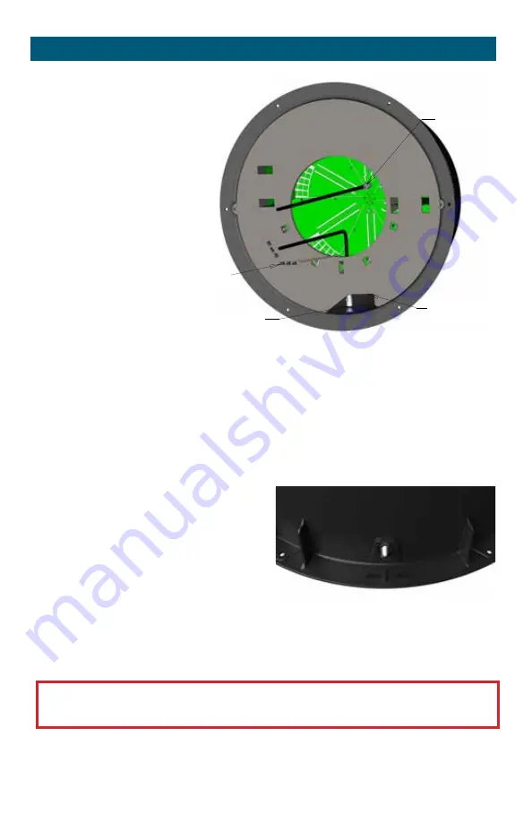
 – Feed the other 3 cables (WiFi and 

4G) down into the roof hole and through 
the ceiling of the RV. While ensuring the 
cables stay in the hole of the RV, position 
the dome so that the domed satellite 
connection is facing the rear of the 
vehicle (figure 4). Satellite bulkhead must 
face rear of RV.

Step 4 

– It is recommended to use butyl tape (not provided) for extra protection under 

the entire flange before screwing to the roof. Screw 6 approved mounting screws* 
into the 6 mounting holes around the flange and into the roof.

*Note: 

Before installing check with the vehicle manufacturer on approved screws.

CAUTION:

 Do not overtighten the mounting screws. This could cause the 

plastic flange to break. 

Step 5 

– Add approved sealant (check with RV manufacturer)  completely around the 

flanged base and over each screw.


continued

Figure 3

SATELLITE CONNECTION

OTA CONNECTION

OPENING FOR WRENCH

WIFI/4G CABLES

OTA 

connection

Opening 

for wrench

Satellite 

connection

WiFi 

cables

Summary of Contents for AIR 360+

Page 1: ...inegard Gateway GW 1000 sold separately Model AR2 V2S Create an account to register your product at winegard com register 2452463 Rev1 4 21 Plus Internet ready Requires Winegard Gateway Router WINEGAR...

Page 2: ...lcome 1 Contents 1 Specifications Features 2 Parts Included 2 Product Information 3 Installation Instructions 3 Power Supply Installation TV Antenna 6 Power Supply Installation Gateway 7 TV Antenna Op...

Page 3: ...ight 7 73 Diameter of dome 17 25 Frequency range VHF 54 to 216 MHz UHF 470 to 700 MHz FM 87 5 108 MHz Gain 18 dB Noise 1 dB Impedance 75 ohms Power supply DC 12 V 1 WiFi antenna 2 LTE antennas For use...

Page 4: ...adcast television once installed but has also been designed with the ability to work with the Winegard Gateway as a WiFi extender and 4G LTE router It is not intended to work with any other router sys...

Page 5: ...flange Failure to install correctly could cause damage to the antenna and possibly the RV A 12 V connection must be made to the back of both power supplies The Winegard Gateway can always be installed...

Page 6: ...wall plate power supply OTA coax and satellite receiver location satellite coax Step 3 Feed the other 3 cables WiFi and 4G down into the roof hole and through the ceiling of the RV While ensuring the...

Page 7: ...ip tie the prewire power cable along with the 4G LTE and WiFi cables to the notch on the backside of the white prewire hole cover Cut the excess length of the zip tie off and make sure all the cables...

Page 8: ...the next level in connectivity For more information please visit winegard com to find a dealer in your area Step 1 Choose a location to install the supplied Gateway wall plate with power On Off switc...

Page 9: ...or Air depending on your TV Make sure you are not on Cable Select Channel Search or Channel Scan Keep in mind that steps to perform a channel scan may vary If the wording in your TV differs from the o...

Page 10: ...FF when connecting disconnecting cables to power supply and antenna but should be turned ON when testing for voltage Step 3 Disconnect cable from antenna and check for 12 VDC at Test Point 1 If there...

Page 11: ...information please visit www winegard com gateway or visit winegard com find a dealer to find a dealer in your area Approved Winegard Satellite Antennas The satellite antenna connection is recommende...

Page 12: ...ufactured by Winegard in any manner whatsoever removing or defacing any serial number usage not in accordance with product instructions or acts of nature such as damage caused by wind lightning ice or...

Reviews: