background image

HOW THE MACHINE WORKS 

 CUTTER 36V   86039100   05/01/07 


The Saber Cutter is a battery powered, self-
propelled, hard floor scrubber intended for 
commercial use.  The appliance applies a 
cleaning solution onto a hard floor, scrubs the 
floor with brushes, and then vacuums the soiled 
water back into the recovery tank. 
 
The machine's primary systems are the solution 
system, scrub system, recovery system, and 
directional control system. 
 
The function of the solution system is to store 
cleaning solution and deliver it to the scrub 
system. The solution system consists of the 
solution tank, strainer, valve and controls.  The 
solution tank stores cleaning solution (water and 
detergent) until it is delivered to the scrub system.  
The strainer protects the valve from debris.  The 
valve is a solenoid type valve, which controls the 
delivery of cleaning solution to the scrub system.  
The valve automatically prevents solution flow 
unless the scrub brushes are turned on and the 
machine is being propelled.  The solution control 
knob controls the amount of cleaning solution 
delivered to the scrub system by controlling the 
amount of time the valve is open. 
 
The function of the scrub system is to scrub the 
floor.  The scrub system consists of two rotary 
type disk scrub brushes, motors, scrub deck skirt, 
lift mechanism and controls.  The brushes scrub 
the floor and the motors drive the brushes.  The 
brush drive hubs allow the scrub brushes to follow 
irregularities and changes in the floor without 
loosing contact with floor.  The scrub deck skirt 
controls the cleaning solution on the floor so that 
the squeegee can pick it up.  The brush lift 
mechanisms and controls are used to raise and 
lower the deck.  


The function of the recovery system is to vacuum 
the soiled water back into the recovery tank.  The 
recovery system consists of the squeegee, 
vacuum motor, float ball filter, recovery tank and 
controls.  The squeegee wipes the dirty solution 
off the floor as the machine moves forward.  The 
vacuum motor provides suction to draw the dirty 
solution off the floor and into the recovery tank. 
The recovery tank stores the dirty solution.  The 
float ball filter protects the vacuum fan from debris 
and shuts off air going to the recovery tank when 
tank is full. When flow of air is shut off the vacuum 
motor will continue to run. At this time the 
recovery tank must be drained. 
 
The function of the directional control system is to 
control the direction and speed of the machine.  
The directional control system consists of the 
propel control buttons, reverse button, speed 
control knob/potentiometer, controller and 
transaxle.  The propel controls actuate switches 
which cause the machine to move forward.  For 
reverse motion depress the reverse button while 
depressing one of the propel controls.The speed 
control knob actuates a potentiometer, which 
signals speed.  The controller interprets the 
forward/reverse signals from the switches and the 
speed signal from the potentiometer to command 
the transaxle to propel the machine in the 
direction, and at the speed, desired. 


3-3 

Summary of Contents for SCEOX326

Page 1: ...before using the machine Lea las instrucciones antes de utilizar la m quina MODELS SCX326 10052400 86039100 02 20 09 PRV NO 98966 AR WALK BEHIND SCRUBBER IPX4 Operating Instructions ENG Instrucciones...

Page 2: ...___ OVERVIEW The Saber Cutter is a battery powered self propelled hard floor scrubber intended for commercial use The appliance applies a cleaning solution onto a hard floor scrubs the floor with brus...

Page 3: ...justing Rear Deflection 4 7 Replacing Aqua Mizer Squeege Blades 4 7 Scrub Brushes 4 8 Types 4 8 Replacing or Installing Scrub Brushes 4 8 Float Shut Off 4 8 Solution Strainer 4 9 Brush Motor Replaceme...

Page 4: ...ts Squeegee Blade Service Schedule The PARTS LIST section contains assembled parts illustrations and corresponding parts list The parts lists include a number of columns of information REF column refe...

Page 5: ...ories shops and offices for more than normal housekeeping purposes Maintenance and repairs must be done by qualified personnel If foam or liquid comes out of machine switch off immediately Disconnect...

Page 6: ...this information carefully Know when these conditions can exist Locate all safety devices on the machine Please take the necessary steps to train the machine operating personnel FOR SAFETY DO NOT OPE...

Page 7: ...wings indicate the location of safety labels on the machine If at any time the labels become illegible promptly replace them 2 GRADE WARNING SEE MANUAL CIRCUIT BREAKER DECAL 86243610 PRV NO 500579 SAF...

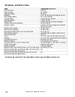
Page 8: ...cm scrub head 16 in 41 cm Scrub brush pressure Actuated 0 lbs to 150 lbs 0 kg to 68 kg Scrub brush speed 200 rpm Tires 2 x 12 in 30 5 cm Non Mark Foam Fill Casters 2 x 4 in 10 2 cm polyurethane Non Ma...

Page 9: ...Pa The weighted root mean square acceleration at the operator s arms was measured to be below 2 5m s2 This was a tri axial third octave band measurement made during normal operation on a composite til...

Page 10: ...llow irregularities and changes in the floor without loosing contact with floor The scrub deck skirt controls the cleaning solution on the floor so that the squeegee can pick it up The brush lift mech...

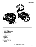
Page 11: ...ntrol Panel 2 Front Cover 3 Recovery Tank 4 Recovery Tank Drain Hose 5 Scrub Head Shrouds 6 Solution Tank 7 Solution Tank Cover 8 Solution Tank Drain Hose 9 Solution Strainer 10 Squeegee 11 Aqua Mizer...

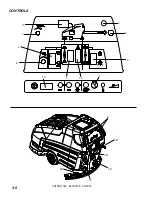
Page 12: ...CONTROLS CUTTER 36V 86039100 05 01 07 3 5 14 10 4 1 13 5 2 9 3 6 8 15 7 16 11 12 12...

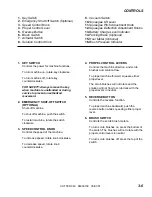
Page 13: ...GENCY SHUT OFF SWITCH OPTIONAL Shuts off machine To shut off machine push the switch To restart machine rotate the switch clockwise 3 SPEED CONTROL KNOB Controls the speed of the machine To increase s...

Page 14: ...each time the scrubbing operation is interrupted 9 VACUUM SWITCH Controls the vacuum motor To start vacuum motor press the bottom of the switch To stop vacuum motor press the top of the switch 10 SQUE...

Page 15: ...After a few minutes of operation the meter will give the correct charge level 14 PARKING BRAKE OPTIONAL Locks front wheels to prevent unintentional movement To set parking brake push down to lock not...

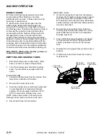
Page 16: ...brakes if your machine is equipped with this option FILLING SOLUTION TANK FOR SAFETY Before leaving or servicing machine stop on level surface turn off machine and remove key 1 Turn the machine power...

Page 17: ...and or reactive metals can cause explosions or fire Do not pick up 1 Turn the machine power on 2 Lower the squeegee 3 Turn the vacuum on 4 Lower the scrub brushes to the floor 5 Turn the scrub brushes...

Page 18: ...e machine power off and set parking brake if your machine is equipped with this option SOLUTION TANK 1 Loosen small drain hose from the retainer then lower hose in direction of the drain 2 Remove the...

Page 19: ...te to allow motor to dry Store with dome off tank to allow the tank to dry Check scrub deck splash skirt Check batteries for corrosion cracks and evidence of overheating Check all bearings for noise C...

Page 20: ...Batteries 2 Squeegee 3 Aqua Mizer 4 Scrub Brushes 5 Recovery Tank Float Shut Off 6 Solution Strainer 7 Brush Motor 8 Traction Motor 9 Circuit Breakers 10 Brush Shroud Brush Skirts 11 Vacuum Motor 12...

Page 21: ...ery cell before and after charging the batteries Never add acid to the batteries use distilled water Do not allow water level to fall below the battery plates Portions of plates exposed to air will be...

Page 22: ...s emit hydrogen gas Explosion or fire can result Keep sparks and open flame away Keep covers open when charging Wear eye protection and protective clothing when working with batteries Charge batteries...

Page 23: ...el It should be up to the indicator ring If necessary add distilled water 11 Lower the battery cover CHANGING BATTERIES Stop the machine in a clean area next to the charger Turn off machine FOR SAFETY...

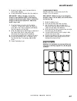
Page 24: ...EE ASSEMBLY 1 With the squeegee in the up position turn key switch OFF 2 Disconnect vacuum hose from squeegee and loosen both knobs 3 Pull squeegee assembly rearward from the lifting carrier 4 Inspect...

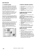
Page 25: ...LECTION 1 Choose a smooth level surface Lower the squeegee and drive forward at least 2 feet 60cm 2 With the squeegee down stop the machine Do not allow machine to roll back FOR SAFETY Before leaving...

Page 26: ...will quickly remove ground in dirt black heel marks and spills When used with the proper stripper this pad leaves the floor clean and ready for finishing The scrub brushes should be checked before ea...

Page 27: ...g bolts located under scrub deck 5 Remove brush motor 6 Reverse steps to install BRUSH MOTOR CARBON BRUSH REPLACEMENT 1 Scribe alignment mark on motor barrel to motor cap Remove two bolts 2 Remove end...

Page 28: ...ully replace brush cap 9 CIRCUIT BREAKERS Circuit breakers interrupt the flow of power in the event of an electrical overload When a circuit breaker is tripped reset it by pressing the exposed button...

Page 29: ...ushes are allowed to wear away completely Periodically check the length of the carbon brushes Replace both carbon brushes when either is less than 3 8 9 5mm long 3 8 9 5mm Vacuum Motor Carbon Brushes...

Page 30: ...he actuator 1 While holding actuator barrel to prevent it from spinning apply power to the actuator such that it is fully extended Positive power to white wire and negative ground to black Limit switc...

Page 31: ...owly Recovery tank full Drain recovery tank Recovery tank float system dirty Clean float system Circuit breaker tripped Reset circuit breaker Loose connection Check motor wires and connections Faulty...

Page 32: ...cted or stuck Clean or replace Vent hole in solution tank lid obstructed Clear obstruction from vent hole No power to machine Battery disconnected Check all battery cable connections Emergency shut of...

Page 33: ...CUTTER 36V 86039100 05 01 07 4 15 THIS PAGE LEFT BLANK INTENTIONALLY...

Reviews: