MAINTENANCE
EXP 98363 10/19/02
13
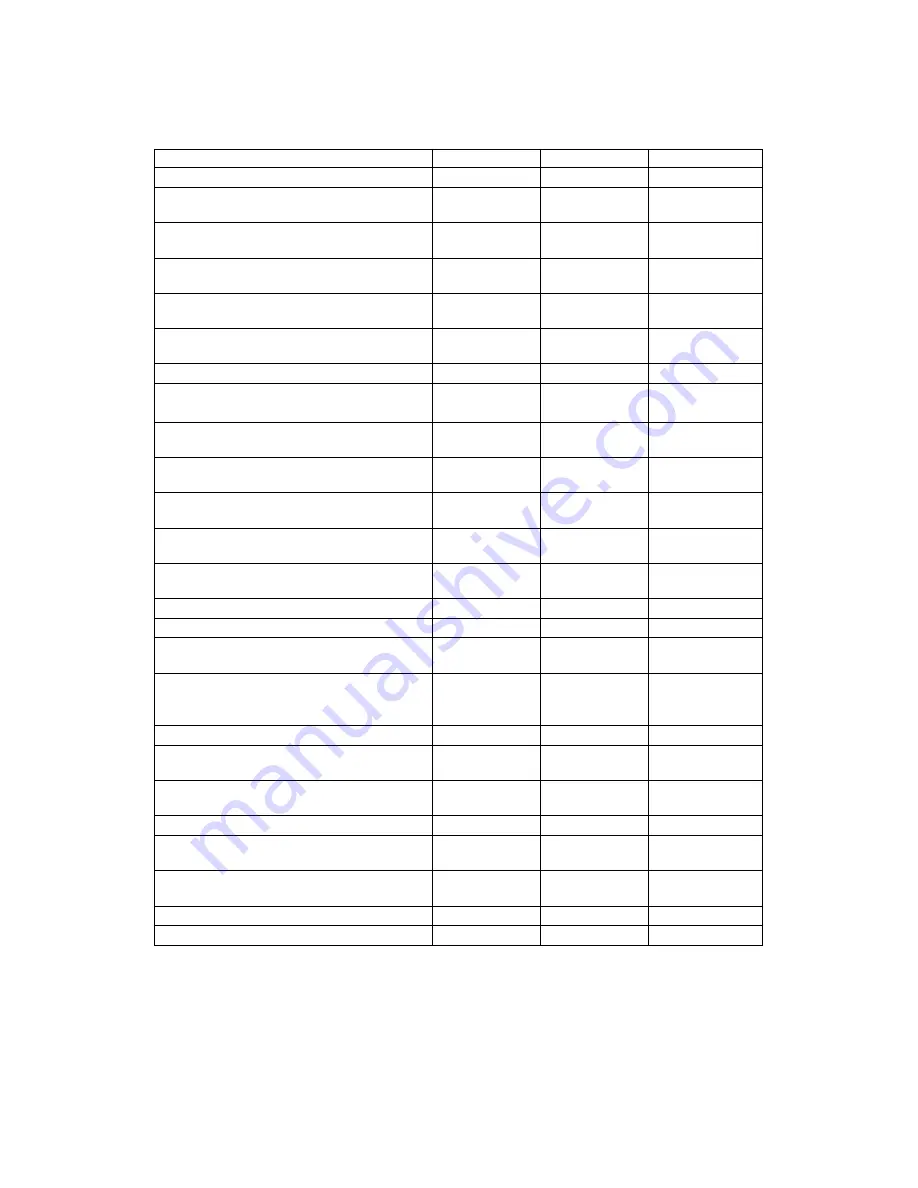
SERVICE SCHEDULE
MAINTENANCE
DAILY
WEEKLY
QUARTERLY
Check machine for cord damage
*
Check recovery dome and gasket for
damage and cleanliness
*
Check brush – should be clean with no
lint or strings attached
*
Inspect vac shoe for blockage; remove
fibers with coat hanger, etc.
*
Check hoses for wear, blockages, or
damage
*
Check handles, switches, and knobs
for damage
*
Check vac motor intake filter and clean
*
Run one gallon of water through
system
*
Clean out recovery tank and check
float valve to make sure it moves freely
*
Clean out solution tank and remove
and clean vacuum intake screen
*
Clean outside of all tanks and check for
damage
*
Run vac motor for at least one minute
to allow motor to dry
*
Store with dome off tank to allow the
tank to dry
*
Check all bearings for noise
*
Check all gaskets for wear and leakage
*
Check vacuum intake screen for
damage; replace if necessary
*
Check pump pressure; observe spray
pattern and check with gauge if
necessary
*
Check and clean solution screen
*
Check belts for wear and replace as
necessary
*
Check brush for wear; ensure bristles
are not damaged
*
Check cables for fraying
*
Check the spray bar (manifold) for
damage; replace if broken or bent
*
Check condition of vac shoe and frame
for damage
*
Check overall performance of machine
*
Check vac motor carbon brushes
*