background image

70

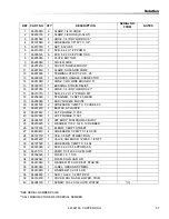
Suggested Spare Parts

PART NO.

DESCRIPTION

SERIAL NO. 

FROM

NOTES

86215250

BELT, 2S 5MM HTD, 15W, 128T

86216050

BRUSH, EXTRACTOR 16"

86295520

BRUSH, EXTRACTOR 16" NATURAL

86002010

BOOT, 3/8 CIRCUIT BREAKER

86001980

BREAKER, 15A 250VAC 50VDC

86215670

BREAKER, 8A VDE CIRCUIT

86218290

GASKET, CONSOLE, HANDLE

86348660

SWITCH, 2-POSN, BRUSH

86007200

SWITCH, DPDT3-POSITION ROCKER

86007140

SWITCH, SPST 2- POSITION ROCKER

86218180

GASKET, DOME 

86003630

FLOAT SHUT-OFF

86299250

ASSY, VAC MOTOR

86298070

ASSY, PUMP 110V

86297440

JET, PROMAX, 11008

86012550

JET, PROMAX, 11001

86201110

PUMP, 110/120 60 HZ FLOJET

86234790

COVER, CLP SOLUTION

86256090

STRAINER, 1/2 FPT 80 MESH

86004570

JET BODY, MINI PROMAX BODY

86293170

WIPER ASM 18"

86297870

ASM, INTERIM SWITCH

ALSO ORDER 86266250 

(QTY 1) & 

86298890 (QTY 1) 

TERMINALS

86302100  CLIPPER DUO

Summary of Contents for 10080480

Page 1: ...Read these instructions before using the machine 86302100 AW 02 01 13 Operating instructions ENG MODELS 10080480 Carpet Extractor...

Page 2: ...racts the soiled solution back into the unit s recovery tank The appliance is fitted with and a hand tool for cleaning upholstery and stairs Warranty Registration Thank you for purchasing a Windsor pr...

Page 3: ...9 Using The Hand Tool 22 Maintenance Service Schedule 23 Components 24 Periodic Maintenance 25 Circuit Protection 26 Scrub Deck 27 Scrub Brush Replacement 28 Vacuum Motor Carbon Brushes 29 Troubleshoo...

Page 4: ...ing condition They are listed in this general order Periodic Daily Regular Troubleshooting The PARTS LIST section contains assembled parts illustrations and corresponding parts list The parts lists in...

Page 5: ...a handle close a door on cord or pull cord around sharp edges or corners Do not run machine over cord Keep cord away from heated surfaces Do not unplug machine by pulling on cord To unplug grasp the e...

Page 6: ...rder le cordon l cart des surfaces chaudes Ne pas d brancher en tirant sur le cordon Tirer plut t la fiche Ne pas toucher la fiche ou l appareil lorsque vos mains sont humides N ins rer aucun objet da...

Page 7: ...ent Report machine damage or faulty operation immediately Do not use the machine if it is not in proper operating condition Following is information that signals some potentially dangerous conditions...

Page 8: ...llance ou d une d t rioration de la machine Ne pas utiliser la machine si celle ci ne fonctionne pas correctement Lire soigneusement les informations ci dessous signalant certains dangers potentiels p...

Page 9: ...ed to connect this plug to a 2 pole receptacle as shown in Fig B if a properly grounded outlet is not available The temporary adaptor should be used only until a properly grounded outlet Fig A can be...

Page 10: ...rtissements et mises en garde importantes qui doivent tre suivis en tout temps Le non respect des avertissements et mises en garde pourrait entra ner des dommages mat riels des blessures graves ou m m...

Page 11: ...watts AC with circuit breaker protection Brushes 2 x 16 406 mm ABS core Perform Alert bristle spiral pattern Cleaning Path 16 40 6 cm Flow Rate Interim 0 09 gpm 0 37 lpm Restorative 1 0 gpm 37 8 lpm S...

Page 12: ...This was a nearfield broad band measurement taken in a typical industrial environ ment on a tile floor This appliance contains no possible source of impact noise The instantaneous sound pressure level...

Page 13: ...interim pump solenoid valve spray jets accessory hand tool and controls The solution tank stores solution until it is delivered through the strainer to the appropriate pump The solenoid valve allows f...

Page 14: ...ons Components 1 Control Panel 2 Recovery Dome 3 Recovery Drain Hose 4 Recovery Tank 5 Scrub Deck 6 Solution Fill Cover 7 Solution Drain Hose 8 Solution Tank 9 Vacuum Shoe 86302100 CLIPPER DUO 1 2 8 6...

Page 15: ...15 Controls 1 Hand Tool Switch 2 Main Switch 3 Light Cleaning 4 Deep Cleaning 5 Continuous Spray 6 Intermittent Spray 7 Intermittent Spray Buttons Operations 86302100 CLIPPER DUO 1 2 3 4 5 6 7...

Page 16: ...ingredients on manufacturer s label before using any product in this machine FILL LINE ADD CLEANING CHEMICAL PER CHEMICAL LABELING STEP 3 REPLACE SOLUTION FILL COVER STEP 4 REMOVE SOLUTION FILL COVER...

Page 17: ...sure dome is seated on recovery tank and float shut off is installed correctly Switch the cleaning mode switch to the desired process A for the encapsulating Interim Carpet Cleaning Process B for Dee...

Page 18: ...ator to hold any one of the three trigger switches in the on position with the fingers and is typically used in small areas where short cleaning passes are made The continuous setting allows the opera...

Page 19: ...rt at wall closest to power outlet For small areas pull straight back without pushing down on handle Release intermittent trigger switches or turn off contin uous setting on solution switch approximat...

Page 20: ...on and vacuum air flow During operation observe the vacuum intake Large amounts of water or foam entering the vacuum system can damage the vacuum motor If you notice either condition shut down the mac...

Page 21: ...Windblower fan Empty recovery tank by releasing recovery drain hose Use a hose with cold water to clean out the recovery tank Also drain solution tank after each use RECOVERY DRAIN HOSE SOLUTION DRAI...

Page 22: ...machine mounted fitting then release collar to lock into place Solution connection can remain connected at all times Disconnect vacuum hose and connect the hand tool to hand tool connection as shown S...

Page 23: ...y tank clean float screen and check float valve to make sure it moves freely Clean out solution Clean outside of all tanks and check for damage Run vac motor for at least one minute to allow motor to...

Page 24: ...nce Components 1 Vacuum Motor 2 Solution Strainer 3A Spray Jet Extraction 3B Spray Jet Interim 4 Interim Solution Pump 5 Main Solution Pump 6 Float Shut off 86302100 CLIPPER DUO RIGHT LEFT BOTTOM 1 2...

Page 25: ...justments or repairs to the machine disconnect the power cord from electrical source 1 Empty unused cleaning solution from the solution tank 2 Flush pumping system with 4 or 7 liters of clean hot wate...

Page 26: ...in the event of an electrical overload When a circuit breaker is tripped reset it by pressing the exposed button If a circuit breaker continues to trip The cause should be found and corrected 15 Amp...

Page 27: ...27 Maintenance Scrub Deck 1 Scrub Brush Motor 2 Scrub Brushes 3 Retaining Clip 4 Brush Installation Decal 86302100 CLIPPER DUO 1 2 3 4...

Page 28: ...hub Bearing Cleaning 1 Remove bearing cap from end of brush 2 Clean cap and bearings Scrub Brush Replacement NOTE See brush placement decal on brush deck Black brush to rear of machine and white brus...

Page 29: ...eed to be replaced or sent to a qualified service center Important These brushes wear quicker as the length shortens due to increased heat Spring inside brush housing will damage motor if brushes are...

Page 30: ...issing Replace as necessary Vacuum hose cracked or hose cuff loose Replace or repair as necessary Recovery tank full float ball stuck in the up position Turn off vac motor Drain and rinse recovery tan...

Page 31: ...31 PARTS 86302100 CLIPPER DUO Parts...

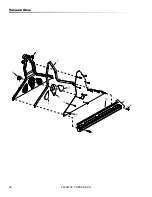
Page 32: ...32 Brush Deck 86302100 CLIPPER DUO...

Page 33: ...T TENSIONER ARM 12 86012780 2 PULLEY ASM 5MM HTD 22T 13A 86216050 1 BRUSH EXTRACTOR 16 13B 86295520 1 BRUSH EXTRACTOR 16 NATURAL 14 86223490 2 RING 10MM EXT SNAP DIN 471 15 86224130 1 SHAFT TENSIONER...

Page 34: ...34 Brush Deck Motor 86302100 CLIPPER DUO...

Page 35: ...TOR ASM 115V INCLUDES 4 16 17 6 86222290 3 NUT 5 16 18 HEX NYLOCK SS 7 86346070 2 COUPLER 2 JAW 35MM 2 WAS 86217250 INCLUDES 9 8 86234600 1 COUPLER SPIDER 2 WAS 86217260 9 86172960 2 SCR SET M6X8 SH I...

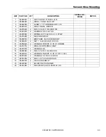
Page 36: ...36 Brush Deck Mounting 1 2 3 4 5 6 7 8 19 10 11 12 2 3 15 16 17 18 4 3 2 13 3 9 14 7 20 21 86302100 CLIPPER DUO...

Page 37: ...CR 5 16 18 X 1 00 CARRIAGE SS 8 86295010 1 BRKT DECK ARM RIGHT 9 86294940 1 BRKT LEFT DECK HANGER 10 86294950 1 BRKT RIGHT DECK HANGER 11 86270990 4 NUT 10 32 HEX NYLOCK 12 86010650 4 WASHER 10 X 9 16...

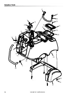
Page 38: ...38 Control Panel 16 26 16 1 2 3 4 6 7 8 11 12 13 14 15 16 17 7 9 19 19 21 22 25 10 18 5 20 24 25 23 86302100 CLIPPER DUO...

Page 39: ...R 24V 115V 11 86224730 1 SPRING COMP 12MM OD X 12 7MM 12 86224930 1 STRAIN RELIEF 14 3 STRAIGHT 13 86007130 1 SWITCH DPDT 2 POSITION ROCKER 14 86007200 1 SWITCH DPDT3 POSITION ROCKER 15 86007140 1 SWI...

Page 40: ...40 Decal 5 1 2 3 4 86302100 CLIPPER DUO...

Page 41: ...Decal REF PART NO QTY DESCRIPTION SERIAL NO FROM NOTES 1 86221470 1 LABEL ACCESSORY 2 86244680 1 LABEL CLIPPER DUO 3 86004970 1 LABEL WINDSOR LOGO DOMED 4 86298670 1 LABEL BRUSH INSTALL 5 86295620 1...

Page 42: ...42 Hand Tool 1 2 3 4 5 86302100 CLIPPER DUO...

Page 43: ...ool REF PART NO QTY DESCRIPTION SERIAL NO FROM NOTES 1 86200810 1 NIPPLE 1 8 FPT QD FEM BRASS 2 86293280 1 HOSE 1 4 RETRACTABLE 3 86293290 1 HOSE ASM 38 1 X 711 BLK VAC 4 86293500 1 HANDTOOL ASM 5 862...

Page 44: ...44 Handle 1 3 5 9 10 2 8 6 7 4 1 1 11 86302100 CLIPPER DUO...

Page 45: ...DLE EXTRUSION 3 86218660 1 HANDLE GRIP 4 86223830 1 SCR M8X40 SHCS ISO 4762 SST 5 86173000 3 SCR KA40X20 PT OVAL WN1412 PL 6 86293400 4 SCR M5X12 SHCS GR 10 9 PLT 7 86218960 1 HOOK UPPER CORD 8 862189...

Page 46: ...46 Handle Bracket 1 2 3 4 5 6 7 8 9 10 11 12 13 14 15 3 4 10 15 16 17 86302100 CLIPPER DUO...

Page 47: ...R HANDLE RELEASE RIGHT 7 86296920 1 BRKT HANDLE TANK MOUNT 8 86296970 1 MECHANISM MOUNT LEFT 9 86296980 1 MECHANISM MOUNT RIGHT 10 86302860 2 SPRING EXT 25D X 1 13L X 031W 11 86298840 1 SCR 10 32 X 1...

Page 48: ...48 Handle Mounting 1 2 3 4 5 6 7 4 2 86302100 CLIPPER DUO...

Page 49: ...ER REF PART NO QTY DESCRIPTION SERIAL NO FROM NOTES 1 86274400 2 SCR 1 4 20 X 5 8 BHCS 2 86006950 6 SCR 10 32 X 1 2 PPHMS BLK NP 3 86276490 6 SCR 5 16 18 X 5 8 HHCS SS 4 86010670 6 WASHER 5 16 FLAT SS...

Page 50: ...50 Handle Release Lever 15 16 17 18 4 4 1 2 3 5 6 7 8 9 10 11 12 13 14 86302100 CLIPPER DUO...

Page 51: ...18020 1 GASKET LEVER HANDLE 7 86221730 1 LEVER PIVOT HANDLE 8 86222280 4 NUT 10 32 HEX NYLOCK SS 9 86295820 2 PIN LEVER SHAFT 10 86221840 1 PIN LINKAGE 11 86222550 1 PIN PIVOT LEVER 12 86222990 1 PLAT...

Page 52: ...52 Recovery Tank 1 2 3 4 5 6 7 8 9 10 11 86302100 CLIPPER DUO...

Page 53: ...SKET 2 86218180 1 GASKET DOME 3 86003630 1 FLOAT SHUT OFF 4 86299180 1 TANK RECVRY DK GRAY TRIMMED 5 86297250 1 HOOK WIREFORM HANDTOOL 6 86006950 2 SCR 10 32 X 1 2 PPHMS BLK NP 7 86004500 1 HOSE CAP 8...

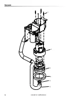
Page 54: ...54 Solution 20 21 18 17 11 4 2 1 3 5 6 7 8 9 10 12 13 14 16 19 14 3 15 15 86302100 CLIPPER DUO...

Page 55: ...6790 2 SCREW 10 32 X 3 8 HHTR W STAR 8 86274290 2 SCR 10 32 X 3 8 PPHMS SS 9 86298840 4 SCR 10 32 X 1 HHMS PLTD 10 86010650 4 WASHER 10 X 9 16 OD 11 86197940 1 HOSEBARB 3 8MPTX1 2 90D DL 12 86294700 1...

Page 56: ...56 Solution 31 35 35 39 37 38 36 14 4 40 40 33 26 25 24 23 22 1 3 3 5 6 31 8 9 10 11 12 13 15 16 18 21 1 2 17 7 7 1 1 1 1 20 2 20 19 27 28 29 30 3 27 32 1 26 1 3 27 27 34 86302100 CLIPPER DUO...

Page 57: ...0710 1 SCR 8 32 X 1 2 PFHMS PLT 18 86256090 1 STRAINER 1 2 NPT 80 MESH 19 86298090 1 ASSY NOZZLE MOUNT 20 86001530 2 HOSEBARB 1 2MPT X 1 2 HOSE 90 21 86297230 1 BAFFLE ACOUSTIC 22 86297440 1 JET PROMA...

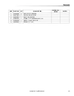
Page 58: ...58 Solution Tank 86302100 CLIPPER DUO...

Page 59: ...R 10 X 1 2 PPHST TYPE B SS 11 86276160 1 SCR 10 32 X 5 8 PPHMS BLK 12 86276290 3 SCR 10 X 3 4 PPHST HI LO BLK 13 86276490 1 SCR 5 16 18 X 5 8 HHCS SS 14 86277050 1 SCR 5 16 18 X 3 4 SHCS SS 15 8624079...

Page 60: ...60 Vacuum Shoe 86302100 CLIPPER DUO...

Page 61: ...E 18 2 86218110 1 GASKET 18 VAC SHOE OUTER 3 86218270 2 GASKET 18 VAC SHOE SIDE 4 86218260 1 GASKET 18 VAC SHOE CENTER 5 86223230 1 PLATE 18 VACUUM SHOE 6 86172950 12 SCR M5X12 SHCS ISO4762 SS 7 86293...

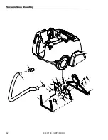
Page 62: ...62 Vacuum Shoe Mounting 86302100 CLIPPER DUO...

Page 63: ...95030 2 SPRING EXT 562D X 6 0L X 072W 8 86278280 2 SHOULDER BOLT 9 86296510 1 BRKT ASM VAC SHOE MOUNT 10 86005810 2 NUT 1 4 20 HEX NYLOCK SS 11 86259420 2 WASHER THRUST 51 ID X 1 ODBRO 12 86272750 1 R...

Page 64: ...64 Vacuum 1 2 3 4 5 6 86302100 CLIPPER DUO...

Page 65: ...PART NO QTY DESCRIPTION SERIAL NO FROM NOTES 1 86300300 4 SCR 8 X 2 PPHSMS 2 86217480 1 COVER VAC MOTOR 3 86299250 1 ASSY VAC MOTOR 4 86002390 1 CLAMP 1 75 WORM GEAR X 312 5 86004290 1 HOSE 1 5 BLK VA...

Page 66: ...66 Wheel Axle 1 2 3 4 5 6 7 2 1 86302100 CLIPPER DUO...

Page 67: ...N SERIAL NO FROM NOTES 1 86276490 5 SCR 5 16 18 X 5 8 HHCS SS 2 86010670 5 WASHER 5 16 FLAT SS 3 86219480 2 HUBCAP 9 75 WHEEL 4 86001660 2 HUBCAP 5 8 SHAFT 5 86226050 2 WHEEL 9 75 X 1 5 6 86010730 2 W...

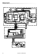
Page 68: ...TTACH TO CTRL BRKT CTRL PNL GRD LUG WHT GRN RED BLU BRN BLK WHT GRN BLK RED BLK HANDLE CONSOLE SWITCH SWITCH SWITCH 1 BLU BLU WHT WHT BLU WHT RED ORG WHT BLU ORG BLK BLK BLK BLU BLU BLU 14 13 9 5 1 BR...

Page 69: ...96020 1 WIRE 150MM RED 18 76031X76046 6 86295980 1 WIRE 605MM BRN 18 76046X76047L 7 86268210 1 WIRE 15 GRN 18 76008 X 76008 8 86295990 2 WIRE 80MM BLU 18 76031X76046 9 86296000 2 WIRE 150MM WHT 18 760...

Page 70: ...660 SWITCH 2 POSN BRUSH 86007200 SWITCH DPDT3 POSITION ROCKER 86007140 SWITCH SPST 2 POSITION ROCKER 86218180 GASKET DOME 86003630 FLOAT SHUT OFF 86299250 ASSY VAC MOTOR 86298070 ASSY PUMP 110V 862974...

Page 71: ...71 86302100 CLIPPER DUO Serial Numbers REF NO MODEL SERIAL 1 10080480 10080480000338 2 10080480 10080480002261 3 10080480 10080480002570...

Page 72: ...72 Notes 86302100 CLIPPER DUO...

Reviews: