


16
BIOS Setup Information
BIOS Introduction
The AMI BIOS (Basic Input / Output System) installed in your computer system’s ROM
supports Intel processors. The BIOS provides critical low-level support for a standard device
such as disk drives, serial ports and parallel ports. It also adds virus and password protection
as well as special support for detailed fine-tuning of the chipset controlling the entire system.
BIOS Setup
The AMI BIOS provides a Setup utility program for specifying the system configurations and
settings. The BIOS ROM of the system stores the Setup utility. When you turn on the
computer, the AMI BIOS is immediately activated. Pressing the <Del> key immediately allows
you to enter the Setup utility. If you are a little bit late pressing the <Del> key, POST (Power On
Self Test) will continue with its test routines, thus preventing you from invoking the Setup. If
you still wish to enter Setup, restart the system by pressing the ”Reset” button or
simultaneously pressing the <Ctrl>, <Alt> and <Delete> keys. You can also restart by turning
the system Off and back On again. The following message will appear on the screen:
Press <DEL> to Enter Setup
In general, you press the arrow keys to highlight items, <Enter> to select, the <PgUp> and
<PgDn> keys to change entries, <F1> for help and <Esc> to quit.
When you enter the Setup utility, the Main Menu screen will appear on the screen. The Main
Menu allows you to select from various setup functions and exit choices.
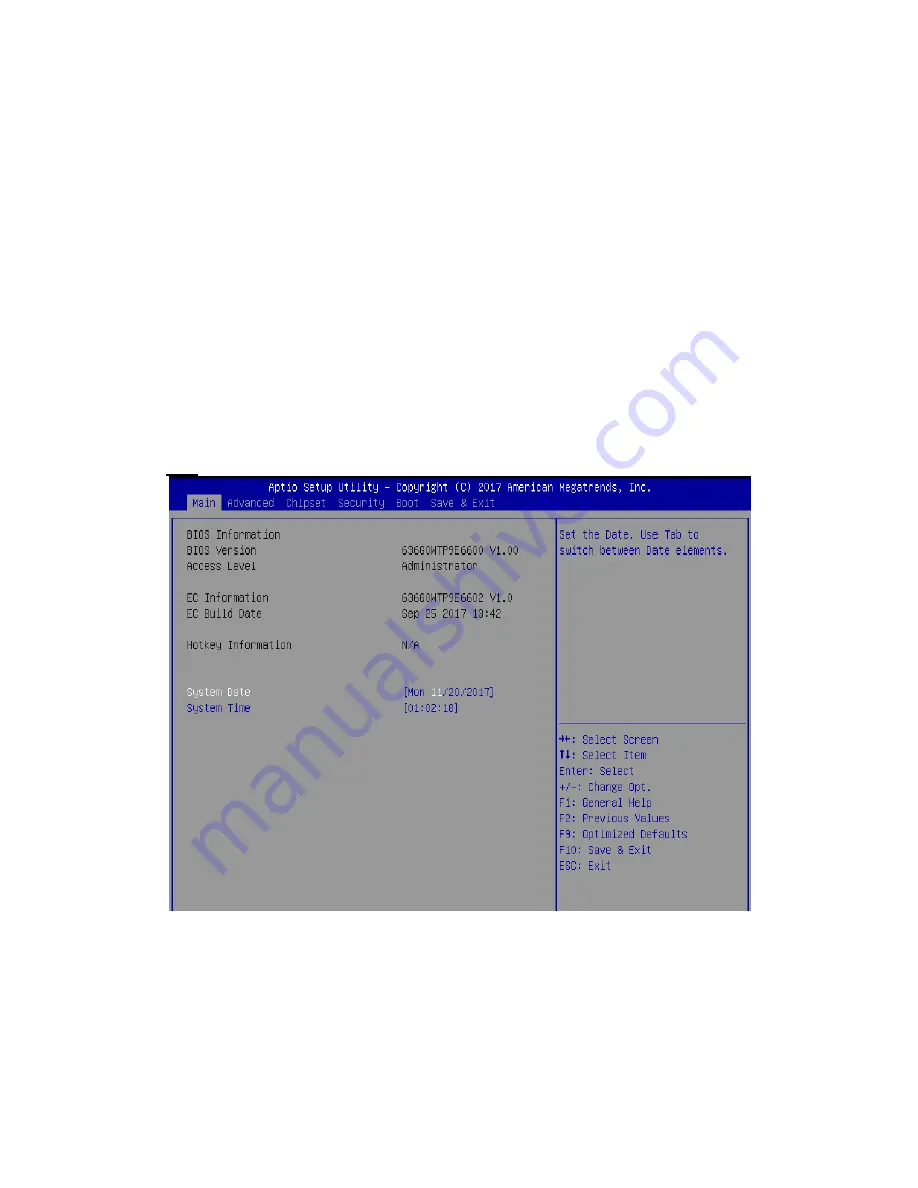
Main
This section provides information on the BIOS information, Embedded controller information and Battery information
System Date
Set the system date. Use the <Tab> key to switch between data elements.
System Time
Set the system time. Use the <Tab> key to switch between time elements.
Summary of Contents for WTP-9E66-15
Page 5: ...Version Change History Date Version Description Remark 2017 11 07 V1 0 First release Ivy...
Page 16: ...10...
Page 17: ...11 System View WTP 9E66 15 Outline Drawing...
Page 18: ...12 WTP 9E66 19 Outline Drawing...
Page 19: ...13 WTP 9E66 22 outline drawing...
Page 39: ...33 PJ5 Power Input Connector Pin Signal Description 1 GND 2 GND 3 DC In 4 DC In...
Page 49: ...43 J22 EC Reset connector Pin Signal Description 1 WRST 2 GND...


