background image

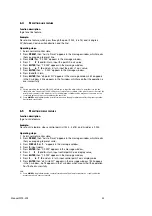
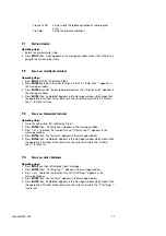
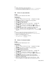
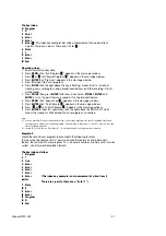
The key index:
0 Program
1

0

2

Point

3

Enter 

4 Enter 
5

Enter


(this index key examples describe a measurement of one point from 

3 points. There are n points. There are n "Enter


"

6

Store

7

1

8

Enter

9

Enter

10 End

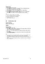
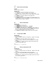
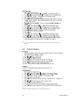
Operating steps:

1. Return normal monitor state;
2. Press 

PROG

, then "Run Program


" appears in the message window;

3. Press


or


until "Record Program


" appears in the message window;

4. Press 

ENTER

then "Prg Num:" appears in the message window;

5. Press 

0

to input No 0 user program;

6. Press 

ENTER

, then the light above the key is flashing, means that it is in state of 

creating new user program, and all valid inputted keys (until the recording is finish) 
will be saved;

7. Press 

POINT

, then press 

ENTER

for 

3

times, at last press 

STORE

1

ENTER

and 

ENTER

in turns, the point feature is saved as No 1 permanent feature.  

8. Press 

PROG

, then "Special Key


" appears in the message window;

9. Press 

ENTER

, then "Finish Record


" appears in the message window;

10. Press 


or


until "Finish Record


" appears in the message window;

11. Press 

ENTER

to input this special key, then the light above the PROG is off, which 

means the creation is finished and No 0 user program is acquired.

Note: 
(1)  you can press QUIT to quit creation before step 6, after step 6 pressing QUIT results in adding QUIT key to 

user program in stead of quit creating program. Not according to the step 8, 9, 10 and 11, user can't exit the 
state of creating program 

(2)  In step 10, you can choose "Quit Record ? " to quit creation and user program is not created.

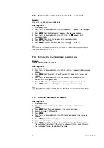
Example 2:  

Create the second user program to accomplish the following functions:
To measure a line feature with "n" points and save the feature as 2nd permanent
feature, then call the 0th user program.("n" is a numeric number, it can be set in internal
system. Use of forward annotation format)

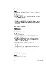
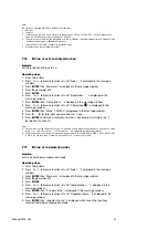
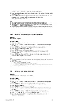
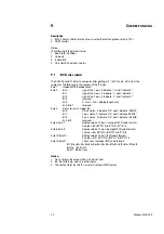
The key index as follow:
1

Program

2

1

3

Line

4 Enter
5

Enter

6

Enter

7

Enter

8

Enter

(This index key example is a measurement of a line from 3

points. 

There are n points, there are n "Enter ? ")

9

Store

10 2
11 Enter
12 Enter
13 Program
14 0
15 End

Manual WDC-300

47

Summary of Contents for WDC-300

Page 1: ...Manual WDC 300 COUNTER FOR WPP 300 ...

Page 2: ...n axis 13 3 3 Finding midpoint 13 3 4 Absolute Incremental mode conversion 14 3 5 Imperial Metric mode conversion 14 3 6 Polar Cartesian conversion 14 3 7 Edge Crosshair conversion 15 3 8 Auto Manual conversion 15 3 9 Browsing graphical features 15 3 10 Storing graphical features 15 3 11 Recalling graphical features 16 3 12 Printing operation 16 4 EXAMPLES FOR MEASUREMENT 17 4 1 Interior system se...

Page 3: ...on mode 39 7 11 Setting up the number points of measuring a point feature 39 7 12 Setting up the number points of measuring a line feature 39 7 13 Setting up the number points of measuring a circle feature 40 7 14 Setting up the count direction of one srecial axis 40 7 15 Resetting the WDC 300 all parameters 40 7 16 Setting up axes scale resolution 41 7 17 Setting up compensation mode 41 7 18 Sett...

Page 4: ... please contact Rational Corporation or it s agents instead of opening WDC 300 s enclosure 2 Never open the WDC 300 s enclosure and the optical plug if the power is on 3 Confirm WDC 300 is connected to ground 0 3 MAINTENANCE 1 Shut off the power supply when clean WDC 300 2 Cleansing with dry cloth or cotton 3 Don t clean the external shuck with toluol or aether 4 Cleaning screen with alcohol or ne...

Page 5: ... entry sequences 12 Preset new points or creat new features 13 Creat or modify program 14 Measure points 15 Measure lines 16 Measure radius diameter and centroid location of circle or arc 17 Measure relative distance 18 Measure angles 19 Define original point 20 Avoids length by manual alignment or fixturing 21 Toggles between polar and certesian modes 22 Toggles between inch and millimeter 23 Tog...

Page 6: ...ALL Recall Recall a permanent feature as temporary feature a0 12 PRINT Print Print current feature or WDC 300 display content 13 SETUP Setup Setup entry 14 ENTER YES ENTER Confirm inputted value or operation 15 CANCEL NO CANCEL Cancel the last inputted value or operation 16 FINISH Finish Finish measure operation or other 17 QUIT Quit Give up an operation 18 0 9 Numeric Number keys 19 Decimal point...

Page 7: ... 6 7 8 9 FG Shield 2 15 pin optional Pin no Signal Wire color 1 5V 2 0V 3 A Brown 4 B Yellow 5 NC 6 FG 7 14 NC 15 ABS 3 7 pin optional Pin no Signal Wire color 1 0V 2 NC 3 A Brown 4 B Yello 5 5V 6 ABS 7 FG 1 5 RS232 PIN DESIGNATION Pin no Signal Wire color 1 GND 2 TXD 3 RXD Brown 4 NC Yellow 5 NC 6 9 NC 6 Manual WDC 300 ...

Page 8: ...XT0 PLUS Yellow 3 The edge detector cause latching the external electric current cause isolated 6 EXT0 RTN Orange 7 EDGE PS Blue 4 The edge detector cause latching TTL Level 8 EDGE GND Black 9 NC 1 7 PRINTER PIN DESIGNATION 15 PD is the standard outlet however the 25 PD is optional 1 15PD outlet PIN Signal Color of cable 1 STROBE Red 2 D0 Brown 3 D1 Yellow 4 D2 Orange 5 D3 Blue 6 D4 Purple 7 D5 Gr...

Page 9: ...ed 2 D0 Brown 3 D1 Yellow 4 D2 Orange 5 D3 Blue 6 D4 Purple 7 D5 Gray 8 D6 White 9 D7 Green 10 ACK Pink 11 BUSY Azury 12 GND Black 13 17 NC 18 25 GND Black Note The pin designation about include that the 15 pin outlet can Change to 25 pin outlet 8 Manual WDC 300 ...

Page 10: ... to catch sample point 2 3 MEASUREMENT MODE WDC 300 has two Measurement Modes Forward Annotation Measurement and Backward Annotation Measurement The Forward Annotation Measurement means that the number less than 50 of sample points are preset before measuring In Backward Annotation Measurement it is not necessary for operator to setup the number of sample points the number of points is decided dur...

Page 11: ...ence 2 8 STORING PARAMETERS WHEN POWER FAILS WDC 300 can store parameters when power fails It can restore the failure state if the power is supplied again Note 1 Temporary feature will be lost automatically if power failed 2 Linear scale cannot be moved after power fails 2 9 MEASURE EASY WDC 300 provides a function Measure Easy When the Measure Easy is open the system can create a feature only inp...

Page 12: ... 000 is displayed in the Y window It indicates a1 is a line the cartesian coordinate of the point is 1 000 1 000 which is nearest from datum It will be changed into 1 414 315 000 in polar Press MORE is displayed in the message window 45 000 is displayed in the X window It indicates the angle between this line and x axis positive direction is 45 000 3 Circle feature A circle feature consists of its...

Page 13: ...age window 45 000 is displayed in the X window 315 000 is displayed in the Y window It indicates the first permanent feature is an angle feature and its value is 45 Press MORE 34 is displayed in the message window 135 000 is displayed in the X window 225 000 is displayed in the Y window 12 Manual WDC 300 ...

Page 14: ...00 works normally it can recall the followings A The last position when power was off B ABS INC Mode C MM INCH Mode D CART POL Mode E EDGE CROSSHAIRS Mode F AUTO MANU Mode G Whether WDC 300 is in skew state or not 3 2 CLEAR ZERO Function description When WDC 300 is in normal monitor state user can setup the current position as the datum point And the new display value will be 0 000 Operating steps...

Page 15: ...ou can t set up INC ABS mode before that you return the normal monitor state 2 If the light above INC ABS is on the current coordinate is INC 3 5 METRIC IMPERIAL CONVERSION Function description toggle between metric mode and imperial mode Operating steps 1 Return normal monitor states 2 Press INCH MM to change mode Note 1 Only in the normal monitor state you can change Metric Imperial mode 2 The c...

Page 16: ...SE MESSAGE OF GRAPHICAL FEATURES Function description To browse message of graphical features Operating steps 1 Return normal monitor states 2 Press or to browse message of features and message is displayed in the message window X window and Y window Note User can t browse message of features until you return normal monitor state 3 10 STORE OPERATION Function description Save temporary feature or ...

Page 17: ... copy of No12 permanent feature Note 1 User can t recall features until you return normal moratoria state 2 In step 2 the message is displayed differently according to actual operation 3 The destine of recall operation is temporary feature a0 3 12 PRINTING Function description Print user program or all graphical features Example 1 Print all graphical features Operating steps 1 Return normal monito...

Page 18: ...cting annotation by steps as forward 1 Press setup enter setup mode 2 Press and to browse menu until Annotation is displayed 3 Press ENTER then Back Annotation is displayed 4 Press or until Forw Annotation is displayed 5 Press ENTER there is a before annotation mode which means this mode is selected 6 Press FINISH to exit And press FINISH again to quit setup 6 Angle unit setting up Angle s unit ha...

Page 19: ...s are probed the system would determine the suitable point Then a0 Point X Y is displayed which means coordinate value of this point is displayed on the X screen and Y screen Press more to get more message 5 Press ORG to set new datum point The light would be on and Select Point is displayed Then the feature probed last is displayed If there is no graphics No Feat Selected is displayed and then qu...

Page 20: ...MEASURING AN ANGLE WDC 300 provides two methods to measure an angle 1 to probe three points to get an angle 2 to probe 2 lines to get an angle 1 To probe three points to get an angle The first sampled point is the vertex of the angle and then measure the second and third point with anticlockwise direct It is important that that the angle can t be more than 180 The following is the working steps 1 ...

Page 21: ...s two points left to be probed if WDC 300 is in the forward annotation mode If in the backward annotation mode Probe 02 is displayed which means being ready to probe the second point 3 Repeat the step 2 until enough points is sampled press FINISH after enough points are probed in backward annotation mode then WDC 300 will calculate parameters of the line based on the probed points Second Line is d...

Page 22: ...yed in the X window the Y coordinate of this point is displayed in the Y window Note 1 Press QUIT to quit the operation 2 The number n in step 2 can be set up in interior setting please refer to 7 10 3 Press POINT more times will increase the number of sample points for point feature 4 Press FINISH to end the operation b Backward Annotation Mode Operating steps 1 Return normal monitor state 2 Pres...

Page 23: ...ge window which indicates that it is waiting for the next point to be sampled 3 Move the linear scale to the measuring point press ENTER then Point n is displayed in the message window n is a number it will plus by 1 automatically after pressing ENTER every time 4 Repeat step 3 during this operation press CANCEL to delete the last sampled point 5 Press FINISH to end the measurement when the number...

Page 24: ... is displayed in the Y window Note 1 Press QUIT to quit the operation 2 Sample mode can be set up in interior system setting 5 4 MEASURING DISTANCE FEATURE a Forward Annotation Mode Operating steps 1 Return to normal monitor state 2 Press DIST then Probe Offset 02 is displayed in the message window which indicates that it is waiting for the next point to be sampled 3 Move the linear scale to the m...

Page 25: ...your time and avoid many errors because of your carelessness The following is the basic operating routine 1 There is one point in need if you want to measure one point only 2 There are two or more than two points to determine a line 3 When more than two points is probed the system would calculate the graphics automatic base on the position of those points Operating steps 1 Return to the normal mon...

Page 26: ...e it immediately WDC 300 will display the value of the coordinate before skew temporary if press SKEW again it will return skew state B If press SKEW for about 3 second minutes release the key after user hears sound bibi the skew will be deleted and you can go on a new skew 3 The object workpiece is skew on an edge or intend on the X axis the Y axis display value will be zero else if the workpiece...

Page 27: ... point of a circle POINT a circle A perpendicular point POINT a point and a line 2 To get a line A line pass through two LINE circle 1 and circle 2 centers of circle A perpendicular to the line pass LINE point and line through the point A perpendicular line to the line LINE The circle and line pass through center 26 Manual WDC 300 ...

Page 28: ...rallel line LINE line and offset A line pass through one point LINE point and angle A line pass through multi point LINE Press or key to select points A line pass through multi circle LINE Press or key to centers select circles 3 To get a circle Aciculate circle CIRCLE the point and a distance Manual WDC 300 27 ...

Page 29: ...cle feature it means that you have selected the circle feature iii Repeat step ii to select another circle feature until you finish with pressing FINISH key iv If the LED show you a message of a0 Circle R D it means that a circle has been constructed A circle constructed with CIRCLE Press or to select existent points multi point 4 Get an offset distance A perpendicular line distance DIST point and...

Page 30: ...circle centers ii The most distance means the most length between two intersects when a line pass through the two circle centers iii The least distance means the least length between two intersects when a line pass through the two circle centers iv Accordingly there are center distance most distance and least distance between a point and a circle and between a line and a circle A perpendicular dis...

Page 31: ...ssage window 7 Press ENTER a0 Point X Y is displayed in the message window which mean that a point feature has been constructed successfully Note 1 In steps 2 the displayed message is in Backward Annotation Mode and the displayed message will be Probe point n in Forward Annotation mode n is a number 2 In steps 3 4 and 6 the displayed message is the information of a0 a3 and a7 and the displayed mes...

Page 32: ...ay Probe Offset 02 means to wait you enter a feature 5 Press or then a0 Circle R D is showed it is the last measured feature C2 6 Press ENTER then is displayed at left of LED window which means that the feature is selected 7 Repeat step 4 and step 5 to select C2 8 Press FINISH to finish The LED will show a message of a0 Distance X Y it means the distance feature has been constructed successfully E...

Page 33: ...hich means that the operation is successfully Note 1 User can press CANCEL to cancel the last preset value or press QUIT to cancel the preset operation 2 If you want to preset the current position of Y axis or Q axis just press Y0 or Q0 in step 3 6 3 PRESETTING POINT FEATURE Function description To get a point feature Example Preset a point feature its coordinate is 1 234 5 678 Operating steps 1 R...

Page 34: ...ch is nearest to the datum point So the displayed coordinate value maybe not the same as the coordinate value you input yet it represent the same line 2 Press MORE to toggle between the point information and the angle information after the preset operation has finished successfully 6 5 PRESETTING CIRCLE FEATURE Function description To get a circle feature Example Preset a circle feature whose cent...

Page 35: ...reset an angle feature whose angle is 45 Operating steps 1 Return normal monitor state 2 Press ENTER then Axis to Preset is displayed in the message window which means that you are going to preset angle 3 Press ANGLE then 0 000 is displayed in the message window 4 Press 4 and 5 in turn input angle s value 5 Press ENTER then a0 Angle 12 is displayed in the message window 45 000 is displayed in the ...

Page 36: ... datum point Example Operating steps 1 Return normal monitor state 2 Press ORG then Select a point is displayed in the message window which means that you are going to preset the datum point 3 Press or to find a temporary features or a permanent feature to be set as the datum point 4 Press ENTER then program return normal monitor state and the new datum point was set at the new position Note 1 Pre...

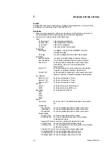
Page 37: ...hen measuring a circle feature Used only in Forward Annotation measurement Axis Direction Reverse X NO Set the count direction of X axis Reverse Y NO Set the count direction of Y axis Reverse Q NO Set the count direction of Q axis Print I F Centro Set the printer port as Centronic port RS232 Set the printer port as RS232 port Baud Rate Set the baud rate of RS232 4800 9600 19200 28800 Super Auto Se...

Page 38: ...EAR ALL PERMANENT FEATURES Operating steps 1 Go to the setup state LED will display Clear 2 Press ENTER then Clr Temp Feat appears in the message window 3 Press or to browse the function list until Clr Perm Feat appears in the message window 4 Press ENTER then Are You Sure appears in the message window 5 Press ENTER then Completed appears in the message window which means that the operation is fin...

Page 39: ...up press CANCEL and then Measure Easy Dis is displayed which means that Measure Easy is close 6 Press FINISH and then QUIT to complete the setup and quit the setup status 7 7 UP ANGLE FORMAT TO DMS Operating steps 1 Go to the setup status 2 Press or to browse function list until Angle Type appears in the message window 3 Press ENTER then DMS Angle appears in the message window 4 Press or to browse...

Page 40: ...ER POINTS OF MEASURING A POINT FEATURE Example Measure three points to get a point feature Operating steps 1 Go to the setup status 2 Press or to browse function list until Annotation appears in the message window 3 Press ENTER then Back Annotation appears in the message window 4 Press or to browse function list until Point Pts 01 appears in the message window 5 Press ENTER then Value 01 appears i...

Page 41: ...en Reverse X YES or Reverse X NO appears in the message window 4 Press or to browse function list until Reverse X YES or Reverse X NO appears in the message window 5 Press CANCEL if Reverse X YES appears in the message window in step 4 Press ENTER if Reverse X NO appears in the message window in step 4 Note If you want to reverse the direction of Y axis in step 4 you should press or to browse the ...

Page 42: ...n Value 0 001000 is displayed in the message window 10 Press 0 0 0 5 to input new resolution for X axis 11 Press ENTER confirm new resolution for X axis then program will return the X Resolution function list Note 1 If user want to set the Encoder Resolution of Y axis and Q axis please repeat the above steps and in step 8 press or until Y Resolution or Q Resolution is displayed in the message wind...

Page 43: ...compensate the error between the measuring value and the standard value 2 These are the operating steps in the linear compensation used to the axes 3 If you want to set the compensation value of Y axis in step 8 Press or to browse function list until Y Compensation is displayed in the message window 4 Calculation of the linear compensation value Measure value standard value Linear compensation val...

Page 44: ...age window 4 Enter password correctly password 332 5 Press ENTER now user enter super setup 6 Press or to browse function list until Prog Lock NO is displayed in the message window 7 Press ENTER then Prog Lock YES is displayed in the message window which mean that the user programs is locked Note 1 After the user program is locked the user programs can t be recorded and edited you can only view or...

Page 45: ...e in step 4 you should browse the function list until Centronic appears in the message window 7 23 SETTING UP RS232 FORMAT Example Set up the transmit mode to pack BCD format Operating steps 1 Enter setup status 2 Press or to browse function list until Super appears in the message window 3 Press ENTER then Password appears in the message window 4 Enter the correct password 332 5 Press the ENTER ke...

Page 46: ... displayed 3 Press ENTER and then 4800 is displayed 4 Press or until 19200 is displayed 5 Press ENTER then v19200 is displayed it means that you have selected the baud rate Note 1 The default baud rate of RS232 is 9600bps 2 If you want to set the baud rate of RS232 to another value in step 4 just select the baud rate format that you want Manual WDC 300 45 ...

Page 47: ...d before the current editing position 7 Up It indicates a is inserted before the current editing position 8 Down It indicates a is inserted before the current editing position 9 Wait Enter It indicates a state waiting for ENTER to be inputted from the panel and the state is inserted before the current editing position 10 Wait Finish It indicates a state of waiting for FINISH to be inputted from th...

Page 48: ...message window 10 Press or until Finish Record appears in the message window 11 Press ENTER to input this special key then the light above the PROG is off which means the creation is finished and No 0 user program is acquired Note 1 you can press QUIT to quit creation before step 6 after step 6 pressing QUIT results in adding QUIT key to user program in stead of quit creating program Not according...

Page 49: ...is acquired Note 1 you should go back to the normal monitor state when the current user program recalls another user program 8 2 EDITING USER PROGRAM Description 1 Editing user program means that user can delete or add keys to the user program s key list after the user program is created 2 Some basic operation in edition state 1 Press or to browse key index 2 Press CANCEL to delete current key 3 P...

Page 50: ...waits for user to press ENTER if Wait Key Enter is displayed in the message window it waits for the measurer to enter FINISH if Wait Key Finish is displayed in the message window Example Run No 1 user program Operating steps 1 Return normal monitor state 2 Press PROG then Run Program appears in the message window 3 Press or until Run Program appears in the message window 4 Press ENTER then Prg Num...

Page 51: ...yte 3 Status error message bit Bit 0 X axis status 0 indicate OK and 1 indicate ERROR Bit 1 Y axis status 0 indicate OK and 1 indicate ERROR Bit 2 Z axis status 0 indicate OK and 1 indicate ERROR Bit 3 Bit7 reserved Byte 4 Byte 7 display value of X axis compact BCD code format X value B4 B5 10 2 B6 10 4 B7 10 6 Byte 8 Byte 11 display value of Y axis compact BCD code format Y value B8 B9 10 2 B10 1...

Page 52: ...tive sign 4 DC3000 sends 60 bytes to the computer after receiving a R from the computer 5 The example show the value of X axes is 30 053mm 9 3 PRINT FORMAT The character v indicates one of the following characters X Y Z R D T A The character d indicates number The character indicates negative sign The character s indicates space 1 Line graphics print format The default setup is mm Position 1 2 3 4...

Page 53: ...mm 184mm 48mm 60mm Power Supply 5 1V DC 5 Optical Signal TTL 50 K Hz Max RS232 9P D interface 5V 1 5V 0 Printer Port Centronix port Edge detector Port TTL or Isolate electric current pulse Pedal Switch Port Short circuit contact 52 W03 134 Manual WDC 300 ...

Page 54: ...W03 134 ...
Reviews: