background image

Powering up a Wilson Amplifier

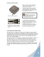
Make sure both the outside and inside 

antenna cables are connected before 

powering up the amplifier.

Connect the power cable from the DC 

plug-in power supply to the amplifier and 

insert the large end into DC power socket 

(the cigarette lighter outlet.)

The amplifier may remain on all the time.  

However,  leaving the amplifier on in a 

vehicle when it is not running can discharge 

the battery in a day or two.

A good option is to power the amplifier 

through the ignition switch so the amplifier 

is turned on and off with the vehicle.

Carefully insert the power cable.

IMPORTANT:  Do not power up the ampli-

fier unless antenna cables are attached to 

amplifier.

Warning: 

Use only the power 

supply provided in this package.  The 

power supply must be 6 V DC.

!

Understanding the Amplifier Lights

If the light turns red, oscillation is occurring and the amplifier has powered down.  

The outside antenna needs to be moved farther from the inside antenna.  Move the 

outside antenna on the roof of the car to the rear of the car, but at least 8-12 inches 

from the rear or side windows.  Remove power from the amplifier and reinstall 

power - this resets the amplifier.
If the light is now green, the oscillation has stopped and the amplifier is working.  If 

the red light is still on, move the antenna farther away and repeat the process.

Always use a magnet-mount or roof-mount antenna.  Do not use a glass-mount 

antenna, as oscillation may cause  continuous shut-down of the amplifier.
An amber light indicates overload from the cell site.  The amplifier has temporarily 

shut down and will automatically reset approximately 1,000 feet or more from the 

cell site.

Summary of Contents for 271230

Page 1: ...6 Attaching a Wilson Inside Antenna Laptop Data Card 7 Optional Cell Phone Cradle Plus 7 Powering Up a Wilson Amplifier 8 Understanding the Amplifier Lights 8 Warnings and Recommendations 9 About Wils...

Page 2: ...n Electronics will pay for delivery of the repaired or replaced product back to the original consumer This warranty does not apply to any amplifiers determined by Wilson Electronics to have been subje...

Page 3: ...amplifier The signal is then boosted and sent through the Ultra slim inside antenna Your cell phone or data card then communicates with the improved signal When the cell phone or data card transmits t...

Page 4: ...ctions in full seek professional help or contact Wilson Technical Support at 866 294 1660 Warning In a wireless installation do not plug the amplifier directly into the cell phone or data card using a...

Page 5: ...easily tuck under the door seal or plastic molding For a more professional looking installation the antenna cable may be run under the door seal Carefully pull down the door seal Run the cable throug...

Page 6: ...the Ultra slim antenna directly on the laptop or cellular data card for maximum signal performance Select a location to install the amplifier that is away from excessive heat direct sunlight or moist...

Page 7: ...place next to the laptop s cellular data card see pg 7 This will maximize the signal strength For a more professional looking installation the Ultra slim antenna may be slid under the seat cover or le...

Page 8: ...or cellular data card If you have questions as to the placement of the Ultra slim antenna call Wilson Technical Support at 866 294 1660 or visit www wilsonelectronics com Amplifier Ultra slim Antenna...

Page 9: ...n this package The power supply must be 6 V DC Understanding the Amplifier Lights If the light turns red oscillation is occurring and the amplifier has powered down The outside antenna needs to be mov...

Page 10: ...ny of the vehicle s occupants or nearby persons and must not be located or operating in conjunction with any other antenna or amplifier All roof mount antennas should be centrally located on the roof...

Page 11: ...g With extensive experience in antenna and amplifier research and design the company s engineering team uses a state of the art testing laboratory including an anechoic chamber and network analyzers t...

Page 12: ...A 18 3 dBm 13 8 dBm GSM 18 1 dBm 14 1 dBm EDGE 18 4 dBm 12 0 dBm AMPS 12 0 dBm 4 Power output for multiple received channels downlink The maximum power is reduced by the number of channels Number of c...

Reviews: