background image

W I L S O N   A U D I O   S P E C I A L T I E S ,   I N C .  


The Surround channel mount has been designed to mount into concrete or at 

least 1.5” thick wood. Depending your wall you may need to reinforce the wall be-

fore attaching the mount to the wall. Use care when attaching the wall mount. If it is 

not attached correctly, it may fall and cause injury.  

M

ARKING

 L

OCATION


• 

Decide how the speaker cables will be routed to the speaker through the 

opening in the mounting bracket or from some other location).

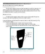
Using the template provided mark the mounting holes on the wall according to Fig-

ures 6.2 and 6.3 below. 


• If you are mounting into concrete mark the outer 5 holes. 


• If you are mounting into a wood surface, mark the 3 center holes.


• 

If you are not mounting into a wall stud but into a wood support, mark the  


outer 5 holes.  

6-4

S

ECTION

 6.2 M

OUNTING


THE

 W

ALL

 B

RACKET

C

EMENT


A

NCHOR

D

RILL

 1/4” 

HOLE

1 3/4” 

DEEP

C

EMENT

 A

N

-

CHOR

D

RILL

 1/4” 

HOLE

1 3/4” 

DEEP

F

IGURE

 6.2- M

OUNTING


LOCATIONS


FOR


A


CONCRETE


WALL

W A T C H   S

U R R O U N D

  O

W N E R

ʼ

S

  M

A N U A L

Summary of Contents for WATCH SURROUND

Page 1: ......

Page 2: ...ooperation with Sales and Marketing The information contained here in is subject to change without notice Current Revi sion 1 0 if you are in need of a more recent manual please contact your dealer Th...

Page 3: ...SIGN 1 4 SECTION 1 2 WATCH PACKAGE 1 4 WATCH CENTER 1 4 WATCH SURROUND 1 5 WATCH SUBWOOFER 1 5 WATCH SUMMARY 1 6 SECTION 2 0 CARE OF THE FINISH 2 1 BREAK IN PERIOD 2 2 BINDING POSTS 2 2 SECTION 3 0 RO...

Page 4: ...L OPTION 5 1 SYSTEM SETUP PROCEDURE 5 1 ZONE OF NEUTRALITY 5 2 SECTION 5 1 CHOOSING A LISTENING POSITION 5 3 SURROUND CHANNEL 5 3 SECTION 6 0 PREPARATION 6 1 SETUP PROCEDURE 6 1 SECTION 6 1 SAFETY WAR...

Page 5: ...ECTION 7 2 INTEGRATING THE WATCH SYSTEM 7 4 INTEGRATING THE WATCH CENTER 7 4 INTEGRATING THE SURROUND CHANNELS 7 5 INTEGRATING THE SUBWOOFER 7 6 SECTION 7 3 TWO CHANNEL FINAL SETUP PROCEDURE 7 7 SECTI...

Page 6: ...UND MOUNTING BRACKET 6 2 FIGURE 6 2 MOUNTING LOCATIONS FOR A CONCRETE WALL 6 4 FIGURE 6 3 MOUNT LOCATIONS FOR WALL STUD OR WOOD SUPPORT 6 5 FIGURE 6 4 SURROUND HARDWARE ATTACHMENT 6 6 FIGURE 6 5 PLACI...

Page 7: ...W I L S O N A U D I O S P E C I A L T I E S I N C...

Page 8: ......

Page 9: ...1 W A T C H I N T R O D U C T I O N...

Page 10: ...W I L S O N A U D I O S P E C I A L T I E S I N C...

Page 11: ...popular multichannel formats WATCH is the rst Wilson system designed from the ground up to excel speci cally at home theater performance Best of all it comes in a package as small or as large as you...

Page 12: ...of its class and is well suited to carry ing on the heritage of Wilson Audio speakers One of David Wilson s most important criteria in speaker development is that a speaker meets the accuracy and dyna...

Page 13: ...ATCH enclosures The en closures of the WATCH system use the same proprietary techniques as have been very successfully used in the X 1 Grand SLAMM MAXX and the WATT PUPPY systems The enclosures are ma...

Page 14: ...nse This is in part a result of Wilson PDC a technology rst developed for Wil son s WAMM and X 1 Grand SLAMM systems and later applied to the rest of the Wilson Line PDC phase delay correction allows...

Page 15: ...masking others Using state of the art materials tech nology rst developed for the X 1 Grand SLAMM WATCH Surround provides stunning results The Surround wall mounting bracket allows the Surround to be...

Page 16: ...you nd what makes Wilson Audio the leader in the in dustry Wilson Audio delivers a product that maintains the strictest structural toler ances durability and reliability You will have consistent repe...

Page 17: ...W I L S O N A U D I O S P E C I A L T I E S I N C 1 7 This page intentionally left blank W A T C H I N T R O D U C T I O N...

Page 18: ......

Page 19: ...C A R E O F T H E W A T C H S U R R O U N D 2...

Page 20: ...W I L S O N A U D I O S P E C I A L T I E S I N C...

Page 21: ...off all loose dust Using the dust cloth as a brush gently whisk off any remaining loose dust Shake out the dust cloth Dust the nish using linear motions in one direction parallel to the oor Avoid usin...

Page 22: ...eak in is complete after 24 hours of playing Playing a disc repeat overnight can accom plish this task quickly Wilson Audio recommends chamber music for this task BINDING POSTS The binding posts used...

Page 23: ...W I L S O N A U D I O S P E C I A L T I E S I N C 2 3 C A R E O F T H E W A T C H S Y S T E M This page intentionally left blank...

Page 24: ......

Page 25: ...3 I N Y O U R R O O M...

Page 26: ...W I L S O N A U D I O S P E C I A L T I E S I N C...

Page 27: ...c sound of the echo in the mid range Slap echo destroys the sound quality of a stereo system primarily in two ways Adding harshness to the upper mid range and treble through energy time storage Destro...

Page 28: ...istic of the room by making it sound deader much heavier in bass tonal balance less bright and alive and quieter These changes usually make the room more pleas ant for conversation but sometimes rende...

Page 29: ...mber of standing waves in a room and is to be avoided for most direct radiator full range loudspeaker systems Some bene t is achieved by placing the stereo pair of loudspeak ers slightly asymmetricall...

Page 30: ...und Reduction of harmonic richness Smearing of lateral sound stage image focus and placement Comb lter effects are usually caused by side wall re ections They are best controlled by very careful speak...

Page 31: ...t louder levels but their contribution to the sound of the speaker is more progressive Rattling windows picture frames lamp shades etc can generally be silenced with small pieces of caulk or with bloc...

Page 32: ......

Page 33: ...4 IN I T I A L SE T U P IN F O R M A T I O N MU L T I CH A N N E L SE T U P...

Page 34: ...W I L S O N A U D I O S P E C I A L T I E S I N C...

Page 35: ...istening position As well as allow you to fully evaluate the acousti cal qualities of your existing room and give you some idea s on how you can im prove your overall system performance SYSTEM SETUP P...

Page 36: ...p from this artifact place a piece of tape on the oor to mark this location You will now be entering the zone of neu trality 4 Continue to walk slowly away from the wall You will hear the beginning of...

Page 37: ...onic results of your listening SPEAKER ORIENTATION Speaker placement and orientation are two of the most important consider ations in obtaining superior sound The rst thing you need to do is minimize...

Page 38: ...er Mounted on stand with no rotation Mounted on stand with longer spikes in the front of stand and shorter spikes in the back allowing the stand and speaker to be rotated up toward the listener Mounte...

Page 39: ...speaker too close to a boundary Nev ertheless we have performed extensive testing on the surround channel and found that signi cant improvement on speaker linearity and integration can be achieved by...

Page 40: ...ft and right speakers and the rear walls A distance of at least 1 1 2 feet should be maintained between the front panel of the left and right speakers and re ective side walls Use of sound absorbent m...

Page 41: ...W I L S O N A U D I O S P E C I A L T I E S I N C 4 7 I N I T I A L S E T U P I N F O R M A T I O N This page intentionally left blank...

Page 42: ...W I L S O N A U D I O S P E C I A L T I E S I N C...

Page 43: ...W I L S O N A U D I O S P E C I A L T I E S I N C 5 IN I T I A L SE T U P IN F O R M A T I O N TW O CH A N N E L SE T U P...

Page 44: ...W I L S O N A U D I O S P E C I A L T I E S I N C...
Page 45: ...t will provide you with valuable information for determining the overall best speaker placements and listening position As well as allow you to fully evaluate the acoustical qualities of your existing...

Page 46: ...to place the speakers Speaking in a moderately loud voice and a con stant volume project your voice out into the room 2 As you move down the wall you will need to have another listener seated in the l...

Page 47: ...I O N SURROUND CHANNEL Wilson Audio has done everything possible to eliminate the boundary interac tions caused by mounting a speaker onto the wall The mounting bracket allows for signi cant improvem...

Page 48: ......

Page 49: ...M o u n t i n g t h e S u r r o u n d 6...

Page 50: ...W I L S O N A U D I O S P E C I A L T I E S I N C...
Page 51: ...ury You will need the following items Supplied hardware kit Tape measure Known listening position Hand Drill SETUP PROCEDURE Note Be careful not to touch the driving elements when you are moving your...

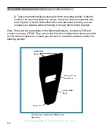
Page 52: ...ur speaker cable by feeding it through the mounting bracket Note There are two geometries of the Mounting Brackets clockwise CW and counter clockwise CCW They refer to the direction of adjustment rota...

Page 53: ...do not proceed with the installation Contact your contractor or an installa tion specialist Wilson Audio has provided two different wall anchors depending on whether you are mounting into wood or conc...

Page 54: ...aker through the opening in the mounting bracket or from some other location Using the template provided mark the mounting holes on the wall according to Fig ures 6 2 and 6 3 below If you are mounting...

Page 55: ...crete drill a pilot hole 1 4 diameter and 1 3 4 deep using provided cement drill bit and a hammer drill Wood drill a 3 16 diameter by 1 3 4 deep pilot hole Remember Have you veri ed the location of al...

Page 56: ...wall by pull ing on the bracket If properly attached the bracket should be able to support 200 lbs SECTION 6 3 PLACING SURROUND Attach the mounting spikes as indicated in Figure 6 4 by screwing them i...

Page 57: ...itioning the lower spike into the lower spike hole lo cated on the mounting bracket see Figures 6 5 6 7 6 7 PLACING SURROUND ON BRACKET FIGURE 6 5 PLACING THE SURROUND CHANNEL ONTO THE MOUNTING BRACKE...

Page 58: ...POSITIONS Note The upper left spike location has 3 different possible locations allowing for some ro tation in towards the listening position Place the spike into the spike hole that is closest to th...

Page 59: ...W I L S O N A U D I O S P E C I A L T I E S I N C W a t c h S u r r o u n d C h a n n e l S e t u p SET LOWER SPIKE INTO 1 4 HOLE GROUNDED INTO LEAD FIGURE 6 7 POSITIONING LOWER SPIKE 6 9...

Page 60: ...e normally Black end of the speaker cable to the high current speaker binding post with the engraved above it Note Do not over tighten the binding posts Overtightening can cause the posts to break off...

Page 61: ...y will cause an unnatural brightness to the sound compromise sound staging perfor mance and may cause instability oscillation and damage in wide bandwidth solid state am pli ers SPADE LUGS The spade l...

Page 62: ...as outlined in Section 7 Section 7 will evalu ate your entire speaker setup and allow you to make small modi cations in speaker rotation and location except of course the Surround channel that will gr...

Page 63: ...W I L S O N A U D I O S P E C I A L T I E S I N C W a t c h S u r r o u n d C h a n n e l S e t u p 6 13 This page intentionally left blank...

Page 64: ......

Page 65: ...7 F I N A L S Y S T E M T U N I N G A N D V O I C I N G...

Page 66: ...W I L S O N A U D I O S P E C I A L T I E S I N C...

Page 67: ...er two channel au dio The multichannel setup will be done as follows Set up of Left and Right Channels with all other speakers disconnect ed Add the Center Channel Add the Surround Channels Add the Su...

Page 68: ...h a lot of low frequency infor mation played at a moderately high level take notes on the sound quality Pay speci c attention to upper and lower bass quality dynamic contrasts im age height and focus...

Page 69: ...quality solo piano recording works well for this step While the music is playing slowly move the speakers left or right 1 inch then 1 2 inch at a time until you achieve the best harmonic integrity Yo...

Page 70: ...Do as follows Place the Center channel centered between the main speakers and even with the front inner edge Set the spikes as indicated in Center channel manual Follow the processor instructions on l...

Page 71: ...rom the Center channel This comb ltering reveals itself as a slight nasal sound in the voice If you notice this in the sound you should raise the front spikes of your center channel until the comb lte...

Page 72: ...r channel and either the Left or Right speakers If the polarity is incorrect you will hear two point sources that are unfocused and located at each speaker playing W A T C H S U R R O U N D O W N E R...

Page 73: ...ce of your speakers Determine the correct rotation as follows Sit in your listening position Make certain to remove the grilles Adjust the rotation of the speakers so that they are ring straight forwa...

Page 74: ......

Page 75: ...8 S Y S T E M S P E C I F I C A T I O N S...

Page 76: ...W I L S O N A U D I O S P E C I A L T I E S I N C...

Page 77: ...ce 8 Ohms see Impedance Curve page 8 2 Sensitivity 89 dB 2 38 V input measured 1m Frequency Response 45Hz to 22kHz Dimensions Height 22 5 Depth Unmounted 8 Depth Mounted 10 5 Width at Top 9 5 Width at...

Page 78: ...W I L S O N A U D I O S P E C I A L T I E S I N C SURROUND CHANNEL IMPENDANCE CURVE 8 2 W A T C H S U R R O U N D O W N E R S M A N U A L...

Page 79: ...W I L S O N A U D I O S P E C I A L T I E S I N C S Y S T E M S P E C I F I C A T I O N S 8 3 This page intentionally left blank...

Page 80: ......

Page 81: ...9 W A R R A N T Y I N F O R M A T I O N...

Page 82: ...W I L S O N A U D I O S P E C I A L T I E S I N C...

Page 83: ...amaged by accident or neglect or in being transported or the defect is due to the product be ing repaired or tampered with by anyone other than Wilson Audio or an authorized repair center Most repairs...

Page 84: ...ars of date of shipment to the dealer is warranted to the rst retain customer to be free of manufacturing defects in materials and workmanship for the same time periods as if the product had originall...

Page 85: ...W I L S O N A U D I O S P E C I A L T I E S I N C This page intentionally left blank...

Page 86: ......

Page 87: ...A T R O U B L E S H O O T I N G G U I D E...

Page 88: ...W I L S O N A U D I O S P E C I A L T I E S I N C...

Page 89: ...check your connec tions for red to red and black to black Play music at a low level and listen to each driver in each channel You may have a driver that is not operating correctly If you nd a driver...

Page 90: ...ed on Check to see if your speaker cables are properly secured Look for frayed ends loose connections a conductor contacting the ampli er chassis Turn the ampli er off and disconnect it from the AC wa...

Page 91: ...Turn the ampli er off and disconnect it from the AC wall outlet Disconnect the speaker cable leads to the ampli er and turn the ampli er on again If the problem is solved You have a short in your spea...

Page 92: ...W I L S O N A U D I O S P E C I A L T I E S I N C...

Page 93: ...W I L S O N A U D I O S P E C I A L T I E S I N C B R E P A I R P R O C E D U R E S...

Page 94: ...W I L S O N A U D I O S P E C I A L T I E S I N C...
Page 95: ...istor as follows 1 Determine which driver is not playing music 2 Remove the appropriate resistor access cover from the enclosure by removing each of the 10 32 button head machine screws see Section 5...

Page 96: ...t damage the enclosure when unsoldering the driver 3 Using a 900 degree F soldering iron heat up the solder joints and remove the driver 4 Melt a small 1 8 diameter bead of solder onto the tip of each...

Page 97: ...W I L S O N A U D I O S P E C I A L T I E S I N C R E P A I R P R O C E D U R E S B 3 This page intentionally left blank...

Page 98: ...W I L S O N A U D I O S P E C I A L T I E S I N C...

Reviews: