background image

English

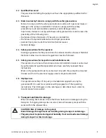
2

Subject to technical alterations!

WILO AG 11/2007

Table of c

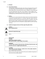
1 General

1.1 About this document

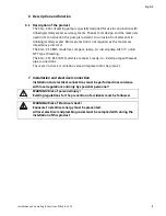
These Installation and Operating Instructions form an integral part of the product. 
They must be kept close to the product and in readiness whenever required. 
Precise observance of these instructions is a pre-condition for use of the product 
for the intended purpose and for its correct operation. These Installation and 
Operating Instructions conform to the relevant version of the equipment and the 
underlying safety standards valid at the time of going to press.

2 Safety

These instructions contain important information which must be followed when 
installing and operating the pump. It is therefore imperative that they be read 
by both the installer and the operator before the pump is installed or started up.
Both the general safety instructions in the ‘Safety precautions’ section and 
those in subsequent sections indicated by danger symbols should be carefully 
observed.

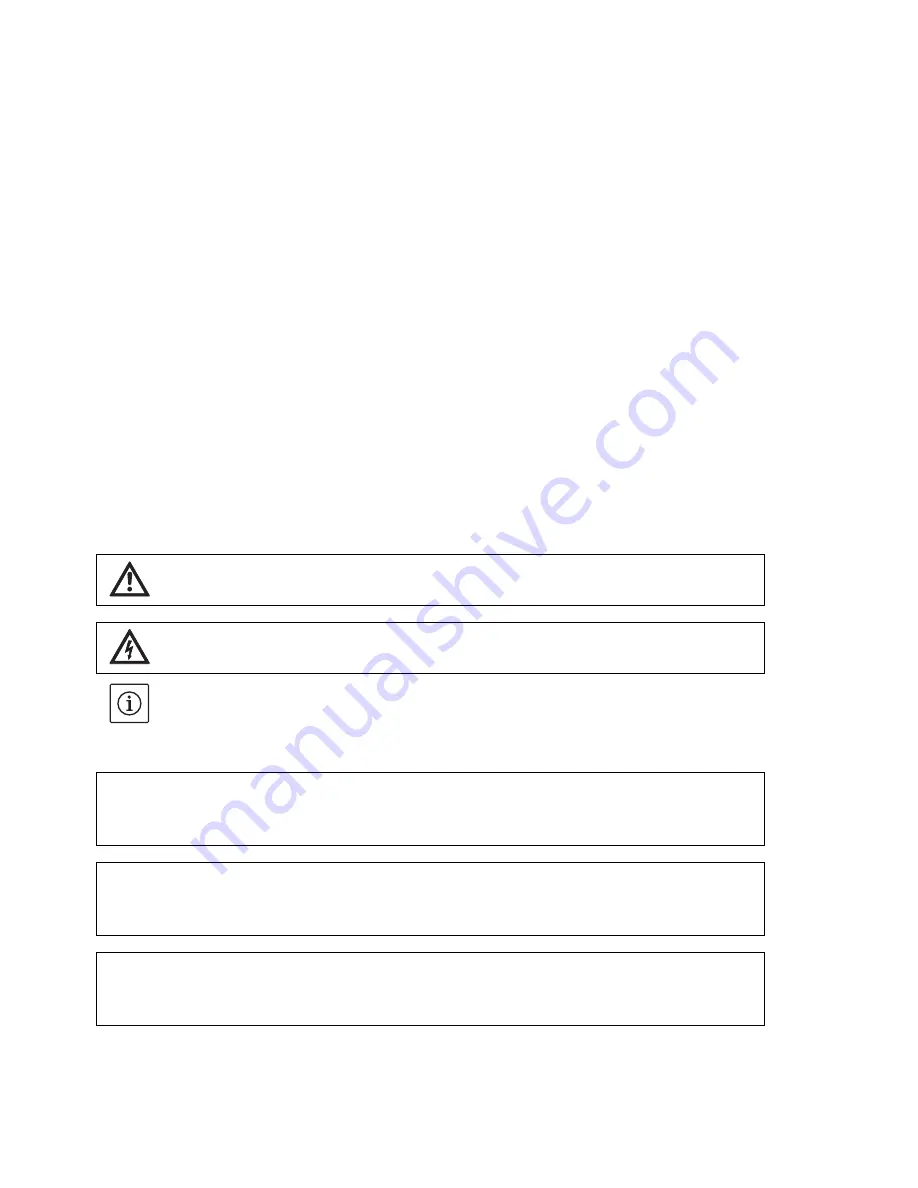
2.1 Symbols and signal words used in these operating instructions

Symbols:


NOTE: ... 

Signal words: 


NOTE: A notice with useful information for the user in relation to the product. It 
alerts the user to possible problems.

General safety symbol

Hazards from electrical causes

DANGER!
Imminently hazardous situation.
Will result in death or serious injury if not avoided.

WARNING!
The user can be exposed to (severe) injury. 'Warning' refers that harm to the 
user when the user is neglecting the procedure.

CAUTION!
The product is at risk of damage. 'Caution' refers to the product when the 
user is neglecting the procedures.

Summary of Contents for Star-Z 15 BN5

Page 1: ...Installation and operating instructions Instructions de montage et de mise en service Instrucciones de instalación y funcionamiento Wilo Star Z 15 4 118 251 Ed 01 2007 11 Kothes ...

Page 2: ......

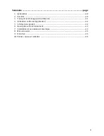
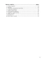
Page 3: ...2 2 Safety 2 3 Transport and interim storage 3 4 Intended use Application 4 5 Product information 4 6 Description and function 5 7 Installation and electrical connection 5 8 Commissioning 7 9 Maintenance 7 10 Faults causes and remedies 8 ...

Page 4: ... is therefore imperative that they be read by both the installer and the operator before the pump is installed or started up Both the general safety instructions in the Safety precautions section and those in subsequent sections indicated by danger symbols should be carefully observed 2 1 Symbols and signal words used in these operating instructions Symbols NOTE Signal words NOTE A notice with use...

Page 5: ...ocal codes and regulations must be followed 2 5 Safety precautions for inspection and installation work The operator must ensure that all inspection and installation work is carried out by authorised and qualified specialists who have carefully reviewed these instructions Work on the pump unit must be carried out only with the pump disconnected locked out from the electrical supply and at complete...

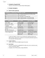
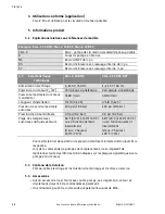
Page 6: ...from Wilo Example Star Z 15 BN5 Star Z 15 BS5 Star Z 15 BS7 Star Z Series Standard drinking water circulating pump B Bronze pump housing N5 NPT union with inch connection S5 Sweat connection with inch internal sweat S7 Sweat connection with inch internal sweat 5 2 Technical data Star Z 15 BN5 Star Z 15 BS5 BS7 Power supply 1 115 V 60 Hz 1 115 V 60 Hz Motor power P 1 W See name plate See name plate...

Page 7: ...l is a compact ready to install pump with union NPT type threading The Star Z 15 BS5 BS7 model is a compact ready to install pump with sweat pipe connections There are no check or isolation valves integrated into the product 7 Installation and electrical connection Installation and electrical connections must be performed in accordance with local regulations and only by specialist personnel WARNIN...

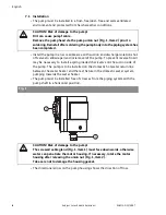
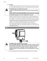
Page 8: ...the last fixture in the domestic water system pumping towards the water heater The pump must be installed free of stresses from the piping system with the pump shaft in a horizontal position The directional arrow on the pump housing shows the direction of flow CAUTION Risk of damage to the pump Dirt can cause pump failure Remove the pump head via the pump union nut Fig 1 Item 2 prior to soldering ...

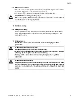
Page 9: ...ld be carried out only by qualified personnel CAUTION Risk of damage to the pump The pump operates at 115 V and must not be connected to a 230 V electrical supply This will result in pump failure WARNING Risk of Electrical shock Exposure to electrical energy must be prevented When carrying out maintenance and repair work the pump must be switched off and protected against unauthorised restarting D...

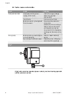
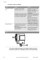
Page 10: ...the supply voltage observe type plate information Fuses faulty Check electrical fuses Motor blocked e g by deposits from the water Disconnect the electrical connection Release the union nut Fig 1 Item 2 remove the motor and impeller and restore movement to the impeller by rotating and flushing out any dirt Noisy pump Motor grinds e g due to depos its from the water Refer to Motor blocked above Dry...

Page 11: ...ransport et stockage avant utilisation 11 4 Utilisation conforme application 12 5 Informations produit 12 6 Description et fonctionnement 13 7 Installation et raccordement électrique 13 8 Mise en service 15 9 Entretien 15 10 Pannes causes et remèdes 16 ...

Page 12: ... connaissance de ces instructions avant de procéder au montage et à la mise en service de la pompe Les instructions de sécurité générale mentionnées dans le présent chapitre sous Consignes de sécurité doivent être respectées de même que les consignes particulièresquifigurent dans lesautres partiesdecemanuel accompagnéesde pictogrammes de danger 2 1 Pictogrammes et termes d avertissement indiqués d...

Page 13: ... sécurité pour les travaux d inspection et de montage L opérateur doit garantir que tous les travaux d inspection et de montage sont effectués par des personnes spécialisées qualifiées ayant prisconnaissance des instructions mentionnées dans ces instrucions Les travaux réalisés sur la pompe ou l installation sont uniquement possibles si la pompe est déconnectée du circuit électrique sécurisée par ...

Page 14: ... peut être commandée séparément auprès de Wilo Exemple Star Z 15 BN5 Star Z 15 BS5 Star Z 15 BS7 Star Z Série pompe de circulation standard de l eau potable B Corps de pompe en bronze N5 Raccord NPT de po S5 Raccord à braser avec ressuage interne de po S7 Raccord à braser avec ressuage interne po 5 2 Caractéristiques techniques Star Z 15 BN5 Star Z 15 BS5 BS7 Alimentation électrique 1 115 V 60 Hz ...

Page 15: ...vec un filetage de type NPT de Le modèle Star Z 15 BS5 BS7 est une pompe compacte prête à l installation avec des raccords à braser pour la tuyauterie Aucun clapet anti retour ou d isolement n est intégré au produit 7 Installation et raccordement électrique Le montage et les raccordements électriques doivent être exécutés conformément aux réglementations locales et uniquement par du personnel spéc...

Page 16: ...omestique avec le pompage en direction du chauffe eau La pompe doit être montée sans tension des tuyauteries avec l arbre de pompe en position horizontale La flèche représentée sur le boîtier de pompe indique la direction du débit ATTENTION Risque d endommager la pompe La présence d impuretés peut provoquer un mauvais fonctionnement de la pompe Avant le soudage retirer la tête de pompe par le biai...

Page 17: ...ar du personnel qualifié ATTENTION Risque d endommager la pompe La pompe est alimentée par une tension de 115 V et ne doit en aucun cas être connectée à une source d alimentation électrique de 230 V Ceci endommagerait la pompe AVERTISSEMENT Risque de choc électrique Il est impératif d éviter toute exposition à l énergie électrique Avant les travaux d entretien et de réparation mettre la pompe hors...

Page 18: ...quées sur la plaque signalétique Calibrage incorrect des fusibles Contrôler les fusibles secteur Le moteur est bloqué en raison par exemple de dépôts d eau Déconnecter l alimentation électrique Desserrer l écrou raccod Fig 1 point 2 retirer le moteur et l impulseur puis rétablir le mouvement vers l impulseur par rotation tout en éliminant les impuretés Pompe bruyante Le moteur grince en raison par...

Page 19: ...eguridad 18 3 Transporte y almacenamiento provisional 19 4 Uso previsto aplicación 20 5 Información de producto 20 6 Descripción y funcionamiento 21 7 Instalación y conexión eléctrica 21 8 Puesta en servicio 23 9 Mantenimiento 23 10 Fallas causas y remedios 24 ...

Page 20: ...nstrucciones antes de instalar o poner en funcionamiento el circulador Deben respetarse cuidadosamente las instrucciones generales de seguridad mencionadas en la sección Advertencias de seguridad y las establecidas en las secciones subsiguientes mediante los símbolos indicadores de peligro 2 1 Símbolos y palabras identificativas utilizados en este manual de funcionamiento Símbolos INDICACIÓN Palab...

Page 21: ... códigos y reglamentos locales 2 5 Advertencias de seguridad para la inspección y el montaje El usuario debe asegurarse de que todos los trabajos de inspección y montaje sean realizados por personas capacitadas y autorizadas que hayan leído atentamente estas instrucciones Sólo se pueden llevar a cabo trabajos en la bomba o la unidad cuando la bomba está desconectada del suministro de corriente elé...

Page 22: ...o Star Z 15 BN5 Star Z 15 BS5 Star Z 15 BS7 Star Z Series Bomba de circulación de agua potable B Cubierta de bomba de bronce N5 Unión NPT con conexión de pulgada S5 Conexión soldada con pulgada de soldadura interna S7 Conexión soldada con pulgada de soldadura interna 5 2 Datos técnicos Star Z 15 BN5 Star Z 15 BS5 BS7 Suministro eléctrico 1 115 V 60 Hz 1 115 V 60 Hz Potencia de motor P 1 W Véase la...

Page 23: ...na bomba compacta y lista para instalar con un tipo de unión roscada NPT de El modelo Star Z 15 BS5 BS7 es una bomba compacta y lista para instalar con conexiones de tubo soldadas No hay válvulas de control ni de aislamiento integradas en el producto 7 Instalación y conexión eléctrica La instalación y las conexiones eléctricas se deben realizar de acuerdo con las regulaciones locales y sólo por pe...

Page 24: ...doméstica que bombea hacia el calentador de agua La bomba se debe instalar sin presiones del sistema de tuberías con el eje de la bomba en posición horizontal La flecha de dirección en la cubierta de la bomba muestra la dirección de la corriente ATENCIÓN Riesgo de dañar la bomba La suciedad puede causar fallas en la bomba Retirar el cabezal de la bomba mediante la tuerca de unión fig 1 elemento 2 ...

Page 25: ...eben realizar por personal cualificado ATENCIÓN Riesgo de dañar la bomba La bomba funciona a 115 V y no se debe conectar a un suministro eléctrico de 230 V Esto causaría fallas en la bomba ADVERTENCIA Riesgo de electrocución Evitar la exposición a la corriente eléctrica Al realizar trabajos de mantenimiento y de reparación la bomba se debe desconectar y proteger contra un nuevo arranque no autoriz...

Page 26: ...rmación de la placa de identificación Falla de fusibles Comprobar los fusibles eléctricos Motor bloqueado por ejemplo a causa de residuos en el agua Desconectar la conexión eléctrica Soltar la tuerca de unión fig 1 elemento 2 retirar el motor y la turbina y restablecer el movimiento de la turbina girando y expulsando la suciedad Ruido en la bomba El motor chirría por ejemplo a causa de residuos en...

Page 27: ...Instructions de montage et de mise en service Wilo Star Z 15 25 Français ...

Page 28: ...LLC 1290 North 25th Ave Melrose Park IL 60160 USA Phone 866 945 6872 WILO USA FAX 708 338 0455 Wilo Canada Inc Bay 7 2915 10th Ave N E Calgary Alberta T2A 5L4 CANADA Phone 866 945 6236 WILO CDN FAX 403 277 9456 ...

Reviews: