background image

12

10 Faults, causes and remedies

Faults, particularly those affecting the pumps or 

the control system, must be remedied by Wilo’s 

customer service or a specialist company

NOTICE!

The general safety instructions must be observed 

during any maintenance or repair work! The instal-

lation and operating instructions of the pumps and 

the control device must be observed!
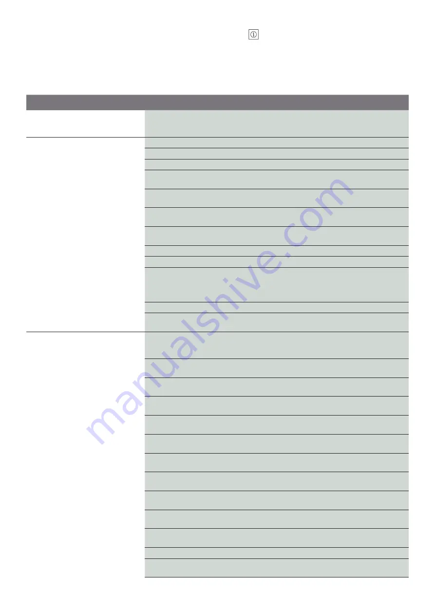
Fault

Cause

Remedy

Display on the control device incorrect

Make use of the information from the installa-

tion and operating instructions for

the control device

Pump(s) do(es) not start

No mains voltage

Check the fuses, cables and connections

Main switch “OFF”

Activate the main switch

Water level in break tank too low, i.e.

Check the break tank’s inlet valve / supply line

Low-water level reached

Check the inlet pressure and the level in the 

break tank

Low water level indicated

Check and, if necessary, replace the low water 

switch

Low water switch defective

Check installation and setting and correct as 

required

Shut-off device closed at pressure sensor

Check and open the shut-off valve if neces-

sary

Start-up pressure set too high

Check the setting and correct it if necessary

Fuse defective

Check fuses and replace if necessary

Motor protection has triggered

Check the default values against the pump or 

motor data, measure the current values and 

correct the setting if necessary. Check the 

motor for defects and replace if necessary

Contactor defective

Check it and replace it if necessary

Turn-to-turn fault in the motor

Check, if necessary replace motor or have it 

repaired

Pump(s) do not switch off

Major fluctuations of the inlet pressure

Check the inlet pressure and take measures to 

stabilise the inlet pressure if necessary (e.g. 

pressure reducers)

Inlet pipe clogged or shut off

Check the inlet pipe and remove the clogging 

or open the shut-off valve if necessary

Nominal diameter of the inlet pipe too

small

Check the inlet pipe and increase the cross 

section of the inlet pipe if necessary

Inlet pipe installed incorrectly

Check the inlet pipe and change the pipe

routing if necessary

Air in the inlet

Check and shut off the piping and vent the 

pumps if necessary

Impellers clogged

Check the pump and replace it or have it

repaired if necessary

Non-return valve leaking

Check and replace the seal or non-return

valve if necessary

Non-return valve clogged

Check and remove the clogging or replace the 

non-return valve if necessary

Gate valve in the system closed or not

sufficiently open

Check and open the shut-off valve completely 

if necessary

Flow rate too high

Check the pump data and default values and 

correct if necessary

Shut-off device closed at pressure sensor

Check and open the shut-off valve if neces-

sary

Switch-off pressure set too high

Check the setting and correct it if necessary

Incorrect direction of rotation of the

motors

Check direction of rotation and correct by

changing over phases if necessary

Summary of Contents for ISAR MODH1 Series

Page 1: ...WILO ISAR MODH1 SCe EM Pioneering for You CD_TE0080 rev00 en Installation and operating instructions...

Page 2: ...dation bearing surface 9 7 2 2 Hydraulic connection and pipes 9 7 2 3 Hygiene 9 7 2 4 Protection against dry running low water level accessories 9 7 2 5 Diaphragm pressure vessel 9 7 2 6 Non pressuris...

Page 3: ...mplies that damage to the product is likely if this information is disregarded NOTICE Useful information on handling the product It draws attention to possible problems Information that appears direct...

Page 4: ...Improper use The operational reliability of the supplied product is only guaranteed if used as intended and in accordance with section 4 of the installation and operating instructions The limit value...

Page 5: ...d name ISAR Product family pressure boosting systems MOD Application commercial H With horizontal pumps 1 Product level 1 entry 3 standard 5 premium 1 Number of pumps CH1 L Pump series 2 Rated flow ra...

Page 6: ...Safety valve BACnet software GSM module mobile communication Float switch Flexible connection pipes Compensators Threaded flanges 6 6 1 Description of the product and accessories General description T...

Page 7: ...r Draining venting Stop valve 6 3 Function of the pressure boosting system Wilo pressure boosting systems in the ISAR MODH1 series are standard equipped with non self priming multistage horizontal cen...

Page 8: ...en the counter nut The system is designed for a maximum ambient temperature of 5 C to 50 C at a relative humid ity of 50 Installation and operation in the vicinity of living rooms and bedrooms is not...

Page 9: ...ly replaced after a long system standstill 7 2 4 7 2 5 7 2 6 For the simple flushing of the system the installa tion of a T connector on the end pressure side of the pressure boosting system is recomm...

Page 10: ...overed by the pipe insulation NOTICE Flexible connection pipes are subject to wear in operation Regular checks for leakages or other defects are necessary Nominal Diameter connection Thread screwed co...

Page 11: ...uctions and accompanying documents for the control device when making this connection and apply the necessary settings In some cases of low volume a float switch will be used This will be factory set...

Page 12: ...k the motor for defects and replace if necessary Contactor defective Check it and replace it if necessary Turn to turn fault in the motor Check if necessary replace motor or have it repaired Pump s do...

Page 13: ...let pipe installed incorrectly Check the inlet pipe and change the pipe routing if necessary Air in the inlet Check and shut off the piping and vent the pumps if necessary Air in the pump Vent the pum...

Page 14: ...alve if necessary Pump s produce s no or too little power Non return valve clogged Check and remove the clogging or replace the non return valve if necessary Gate valve in the system closed or not suf...

Page 15: ...ation It means that the electrical and electronic products in question must not be disposed of along with domestic waste To ensure proper handling recycling and disposal of the used products in questi...

Page 16: ...16 Fig 1 Fig 1b Fig 1c...

Page 17: ...sed break tank on the inlet side 22 N A 28 Flushing apparatus for inlet connection of thebreak tank 23 Diaphragm pressure vessel on the discharge side 29 Bypass for inspection maintenance not permanen...

Page 18: ...MEDANA CH1 L 207 1 E E 10N EP 4231511 l l MEDANA CH1 L 402 1 E E 10N EP 4231513 l l MEDANA CH1 L 403 1 E E 10N EP 4231515 l l MEDANA CH1 L 404 1 E E 10N EP 4231517 l l MEDANA CH1 L 405 1 E E 10N EP 42...

Page 19: ..._ Pressure Equipment Safety Regulations SI 2016 No 1105 _ Electromagnetic Compatibility EMC Regulations SI 2016 No 1091 amended _ Restriction of the Use of Certain Hazardous Substances RoHS in Electr...

Page 20: ...h hungsanlagen der Baureihen Nous fabricant d clarons sous notre seule responsabilit que les types de surpresseurs des s ries Isar MODH1 1CH1 L SCe EM Isar MODH1 2CH1 L SCe EM Isar MODH1 3CH1 L SCe EM...

Page 21: ...21 NOTES...

Page 22: ...e 100 D 44263 Dortmund Germany T 49 231 4102 0 F 49 231 4102 7363 wilo wilo com www wilo com WILO UK Centrum 100 Second Avenue Burton Upon Trent Staffordshire DE14 2WJ T 44 1283 523 000 F 44 1283 523...

Reviews: