


Page 16
Rev. 1/2019
www.willoughby-ind.com
Installation & Operation Manual
Aquafount
®
180° Washfountain
WAF-5403 Series / WAF-5404 Series
Willoughby Industries, Inc.
TOLL FREE
(800) 428-4065
● LOCAL
(317) 875-0830
● FAX
(317) 875-0837
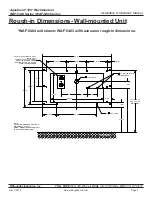
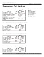
Installation Instructions (cont.)
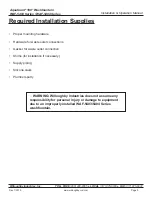
Parts supplied:
• Valve Assembly (pre-installed)
• 3/8" x 4' Multi-Colored Water Lines
• Small Diameter Multi-Colored Pneumatic Tubing
• 1/4-20 x 1/2" security screws
• 1/4-20 tinnerman nuts
Note: Use wire tie mounts and wire ties to route
and secure wiring. Wires are long enough to
accommodate various routing paths. Longer
tubes may need to be bundled with wire ties so
they do not come in contact with sharp corners.
INSTALLATION INSTRUCTIONS
Visit our website at http.//www.willoughby-ind.com
2210 West Morris Street • P.O. Box 21217 • Indianapolis, IN 46221
(317) 638-2381 • Fax: (317) 638-6110 • (800) 428-4065
© Rev. 1/2007
Page 6
Parts supplied:
· Valve Assembly
Plug-In Transformer
Terminal Block Plate
4’ x 3/8" multi-colored water lines
· ¼-20 x ½” security screws
· ¼-20 tinnerman nuts
· Wire ties
· Wire tie mounts (adhesive backed)
1.) Locate terminal block plate and attach to pedestal using ¼-20 x ½” security screws and
tinnerman nuts.
2.) Locate the group of loose colored wires coming from the terminal block plate labeled “UPPER”.
3.) Feed two like-colored wires into each of the actuator housing assembles.
Note: Use wire tie mounts and wire ties to route and secure wiring. Wires are long enough to
accommodate various routing paths. Longer wires may need to be bundled with wire ties so that
they do not come in contact with sharp corners.
4.) Plug both like-colored wires into the actuator as shown above (either wire will work on each
connector).
5.) Locate the 3/8" x 4’ colored tubing water lines. Match up the color of tubing with the color of wire
and run the tubing into each of the actuator housings. Loosen the plastic nut and firmly push the
tubing into the elbow connector located in each spray head. Tighten nut securely. Repeat for
each spray head, being sure to match each of the colors together (wire and tubing).
6.) Connect each set of like-colored wires and tubing to each of the manifolded valves.
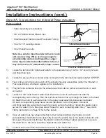
STEP FOUR-A
Connections for Infrared / Piezo Actuators
Infrared
Piezo
© Rev. 5/2010
Piezo Push Button Actuator
INSTALLATION INSTRUCTIONS
Visit our website at http.//www.willoughby-ind.com
2210 West Morris Street • P.O. Box 21217 • Indianapolis, IN 46221
(317) 638-2381 • Fax: (317) 638-6110 • (800) 428-4065
© Rev. 1/2007
Page 6
Parts supplied:
· Valve Assembly
Plug-In Transformer
Terminal Block Plate
4’ x 3/8" multi-colored water lines
· ¼-20 x ½” security screws
· ¼-20 tinnerman nuts
· Wire ties
· Wire tie mounts (adhesive backed)
1.) Locate terminal block plate and attach to pedestal using ¼-20 x ½” security screws and
tinnerman nuts.
2.) Locate the group of loose colored wires coming from the terminal block plate labeled “UPPER”.
3.) Feed two like-colored wires into each of the actuator housing assembles.
Note: Use wire tie mounts and wire ties to route and secure wiring. Wires are long enough to
accommodate various routing paths. Longer wires may need to be bundled with wire ties so that
they do not come in contact with sharp corners.
4.) Plug both like-colored wires into the actuator as shown above (either wire will work on each
connector).
5.) Locate the 3/8" x 4’ colored tubing water lines. Match up the color of tubing with the color of wire
and run the tubing into each of the actuator housings. Loosen the plastic nut and firmly push the
tubing into the elbow connector located in each spray head. Tighten nut securely. Repeat for
each spray head, being sure to match each of the colors together (wire and tubing).
6.) Connect each set of like-colored wires and tubing to each of the manifolded valves.
STEP FOUR-A
Connections for Infrared / Piezo Actuators
Infrared
Piezo
© Rev. 5/2010
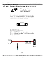
Infrared Sensor Actuator
1.) Locate the terminal block plate and attach to the pedestal using 1/4-20 x 1/2" security screws
and tinnerman nuts�
2.)
Locate the group of loose colored wires coming from the terminal block plate labeled "UPPER".
3.)
Feed 2 like-colored wires into each of the actuator housing assemblies (either the Infrared or
Piezo assemblies, whichever applies to the installation).
4.)
Plug both like-colored wires into the actuator as shown above (either wire will work on each
connector)�
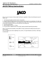
5.)
Locate the 3/8" multi-colored water lines. Match the color of each water line with the
corresponding color of wiring� Run the end of each water line up through the basin to the head
kit. Match the color of each water line to the spray head assembly below each actuator.
On each corresponding spray head, loosen the plastic nut on the plastic connector
and firmly push the water line through the plastic nut into the fitting. Tighten the plastic nut to
secure the water line to the spray head. Repeat for each remaining water line. (**see JACO
Fitting Instructions on Page 19 for further detail)�
6.)
Once all water lines have been attached to their corresponding spray heads, on each
corresponding manifolded valve assembly, loosen the plastic nut on the plastic connector and
firmly push the water line through the plastic nut into the fitting. Tighten plastic nut to secure
the water line to the valve assembly� Repeat for each water line�
7.)
Connect each set of like-colored wires to each of the manifolded valves.
Step 4A: Connections for Infrared/Piezo Actuators


