430 Ink Jet Printer Service and Maintenance Manual
46
Issue 2
Part No. 306-0430-102
Table 36 PSU Board General Specification
Table 37 PSU Board Output Specifications
Main Assemblies
The printer comprises four main assemblies:
•
Cabinet.
•
Printhead.
•
Electronics
system.
•
Ink
system.
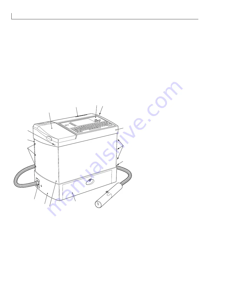
Cabinet
(
1
) Reservoir filler cover
(
2
) Vent
(
3
) Control
panel
(
4
) Top cover fastener
(
5
) Top
cover
(
6
) Side cover fasteners
(
7
) Connector
panel
(
8
) Filter
cover
(
9
) Side
cover
(
10
) Base
1
2
4
5
6
7
9
6
3
8
9
10
11
4
(
11
) Umbilical outlet
Figure 17 Printer Cabinet
Top Cover
The top cover (
5
) is moulded from a plastic material and houses the following:
The control panel (
3
).
A hinged reservoir filler cover (
1
) that gives access to the ink and top up reservoir fillers.
A vent (
2
) that allows heat and vapour to escape from the enclosure.
The top cover is secured in position by two fasteners (
4
) which are screwed in to release the cover. When raised,
the top cover is supported on two telescopic struts, which gives access to the internal components of the printer.
Summary of Contents for 430
Page 1: ...430 Ink Jet Printer Service Manual THE WORLD S CODING AND LABELLING COMPANY ...
Page 7: ...430 Ink Jet Printer Service and Maintenance Manual vi Issue 2 Part No 306 0430 102 ...
Page 17: ...430 Ink Jet Printer Service and Maintenance Manual xvi Issue 2 Part No 306 0430 102 ...
Page 31: ...430 Ink Jet Printer Service and Maintenance Manual 14 Issue 2 Part No 306 0430 102 ...
Page 61: ...430 Ink Jet Printer Service and Maintenance Manual 44 Issue 2 Part No 306 0430 102 ...
Page 161: ...430 Ink Jet Printer Service and Maintenance Manual 144 Issue 2 Part No 306 0430 102 ...
Page 181: ...430 Ink Jet Printer Service and Maintenance Manual 164 Issue 2 Part No 306 0430 102 ...
Page 200: ... ...
Page 202: ... ...


