Wilden T2 Original Metal Manual Download Page 13

11

SECTION 8A

T2 METAL

DIRECTIONS FOR DISASSEMBLY/REASSEMBLY
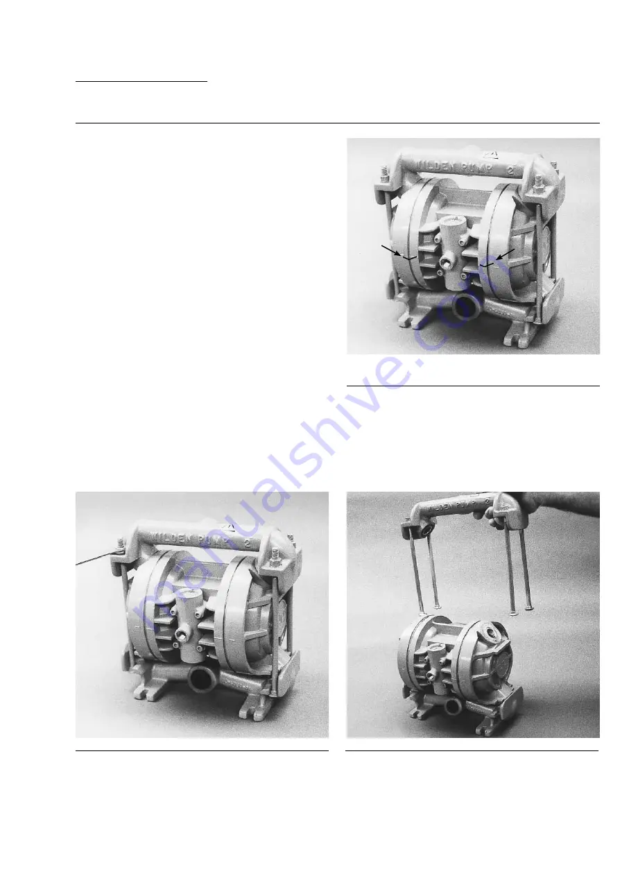
Figure 1

Step 2. 

Figure 2

Utilizing the 9/16” box wrench, start by removing the four long 
carriage bolts that secure the top and bottom manifolds to the 
center section.

Step 3. 

Figure 3

Remove the top manifold and lift the center section off the inlet 
manifold.

CAUTION:

  Before any maintenance or repair is attempted, the 

compressed air line to the pump should be disconnected and 
all air pressure allowed to bleed from the pump. Disconnect 
all intake, discharge, and air lines. Drain the pump by turning 
it upside down and allowing any fluid to flow into a suitable 
container. Be aware of any hazardous effects of contact with 
your process fluid.

The Wilden model T2 has a 25 mm (1”) inlet and 19 mm (3/4”) 
outlet and is designed for flows up to 132 lpm (35 gpm). The 
single-piece center section, consisting of center block and 
air chambers, is molded of polypropylene or aluminum. The 
air valve is manufactured of brass or high-tech, engineered 
thermoplastics. All o-rings used in the pump are of a special 
material and shore hardness that should only be replaced with 
factory-supplied parts.

TOOLS REQUIRED:

Adjustable Wrench
9/16” Box Wrench
3/4” Box Wrench
Vise equipped with soft jaws (such as plywood, plastic
or other suitable material)

NOTE:

 The model used for these instructions incorporates 

rubber diaphragms, balls, and seats. Models with PTFE 
diaphragms, balls and seats are the same except where 
noted.

DISASSEMBLY:

Step 1.

Before starting disassembly, mark a line from each liquid 
chamber to its corresponding air chamber. This line will assist 
in proper alignment during reassembly.

WIL-10200-E-03

WILDEN PUMP & ENGINEERING, LLC

Summary of Contents for T2 Original Metal

Page 1: ...T2 WIL 10200 E 03 REPLACES EOM T2M 10 03 EOM S i m p l i f y y o u r p r o c e s s Engin e e ri n g Operati o n Mainte n a n ce Original Series METAL Pumps...

Page 2: ...S DATA 7 SECTION 7 INSTALLATION AND OPERATION A Installation 8 B Operation Maintenance 9 C Troubleshooting Pumps 10 SECTION 8 DIRECTIONS FOR DISASSEMBLY REASSEMBLY A T2 METAL Disassembly Cleaning Insp...

Page 3: ...o make sure all pipe line debris is clear Use an in line air filter A 5 micron air filter is recommended NOTE Tighten clamp bands and retainers prior to installation Fittings may loosen during transpo...

Page 4: ...oprene Orange Dot VALVE SEAT A ALUMINUM S STAINLESS STEEL VALVE SEAT O RING BN BUNA N EP EPDM FS SANIFLEX Hytrel Cream PU POLYURETHANE Brown TF PTFE White WF WIL FLEX Santoprene LEGEND T2 X X X X X XX...

Page 5: ...2 When the pressurized diaphragm diaphragm A reaches the limit of its discharge stroke the air valve redirects pressurized air to the back side of diaphragm B The pressurized air forces diaphragm B aw...

Page 6: ...ch A 267 10 5 B 36 1 4 C 137 5 4 D 254 10 0 E 279 11 0 F 28 1 1 G 97 3 8 H 76 3 0 J 185 7 3 K 211 8 3 L 173 6 8 M 107 4 2 N 127 5 0 P 8 0 3 R 33 1 3 DIMENSIONS ITEM METRIC mm STANDARD inch A 267 10 5...

Page 7: ...EM METRIC mm STANDARD inch A 264 10 4 B 36 1 4 C 137 5 4 D 257 10 1 E 267 10 5 F 295 11 6 G 41 1 6 H 97 3 8 J 74 2 9 K 183 7 2 L 211 8 3 M 173 6 8 N 107 4 2 P 127 5 0 R 8 0 3 S 43 1 7 T2 METAL SANIFLO...

Page 8: ...of the pump performance curve Height 279 mm 11 0 Width 267 mm 10 5 Depth 185 mm 7 3 Est Ship Weight Aluminum 12 kg 26 lbs Stainless Steel 16 kg 36 lbs Air Inlet 6 mm 1 4 Inlet 25 mm 1 Outlet 19 mm 3...

Page 9: ...chart Caution Do not exceed 8 6 bar 125 psig air supply pressure Flow rates indicated on chart were determined by pumping water For optimum life and performance pumps should be specified so that dail...

Page 10: ...nal determination of the pump site should not be made until the piping problems of each possible loca tion have been evaluated The impact of current and future installations should be considered ahead...

Page 11: ...rs and replacements Over a period of time such records can become a valuable tool for predicting and preventing future maintenance problems and unscheduled downtime In addition accurate records make i...

Page 12: ...Wilden suggests the use of an oil with arctic characteristics ISO 15 5 wt Pump runs but little or no product flows 1 Check for pump cavitation slow pump speed down to match thickness of material being...

Page 13: ...inlet and 19 mm 3 4 outlet and is designed for flows up to 132 lpm 35 gpm The single piece center section consisting of center block and air chambers is molded of polypropylene or aluminum The air va...

Page 14: ...ched or gouged Using an adjust able wrench remove diaphragm assem bly from shaft Inspect all parts for wear and replace with genuine Wilden parts if necessary Step 4 Figure 4 Remove the discharge valv...

Page 15: ...ving the four socket head cap screws which attach it to the center section The piston in the air valve is aluminum with a dark anodized coating see Figure A The piston should move freely and the ports...

Page 16: ...page The following tips will assist in the assembly process Clean the inside of the center section shaft bushing to ensure no damage is done to new seals Stainless steel bolts should be lubed to redu...

Page 17: ...15 WIL 10200 E 03 WILDEN PUMP ENGINEERING LLC...

Page 18: ...16 SECTION 9A EXPLODED VIEW PARTS LISTING T2 METAL AIR OPERATED RUBBER TPE FITTED WILDEN PUMP ENGINEERING LLC WIL 10200 E 03...

Page 19: ...0 03 04 6400 03 N A N A N A N A 11 Center Section Glyd Ring 4 02 3210 55 225 02 3210 55 225 02 3210 55 225 02 3210 55 225 02 3210 55 225 02 3210 55 225 02 3210 55 225 12 Shaft 1 02 3800 03 07 02 3800...

Page 20: ...18 27 26 17 23 24 25 16 20 21 22 18 19 SECTION 9B EXPLODED VIEW PARTS LISTING T2 METAL AIR OPERATED PTFE FITTED WILDEN PUMP ENGINEERING LLC WIL 10200 E 03...

Page 21: ...2 6000 03 Hex Nut 1 4 20 Not shown 4 04 6400 08 04 6400 03 04 6400 03 N A N A N A 11 Center Section Glyd Ring 4 02 3210 55 225 02 3210 55 225 02 3210 55 225 02 3210 55 225 02 3210 55 225 02 3210 55 22...

Page 22: ...1080 52 N A 02 1200 52 Neoprene 02 1010 51 02 1080 51 N A N A EPDM 02 1010 54 02 1080 54 N A 02 1200 54 Viton 02 1010 53 02 1080 53 N A N A Wil Flex 02 1010 58 02 1080 58 N A 02 1200 58 Sani ex 02 10...

Page 23: ...comes rst Failure due to normal wear misapplication or abuse is of course excluded from this warranty Since the use of Wilden pumps and parts is beyond our control we cannot guarantee the suitability...

Reviews: