


INSTRUCTION MANUAL
NI-210WE
Rev. 4 04/20
3 di 6
The test instrument should have a measurement range
approximately equal to or slightly wider than the pressure switch
range and should have an accuracy consistent with the accuracy
required to calibrate the set point.
For example DW03 range 0,7/16mbar the accuracy of the test
gauge must be ± 0,04 mbar to calibrate the set point with an
accuracy of ± 0,16 mbar (1% of the adjustable span).
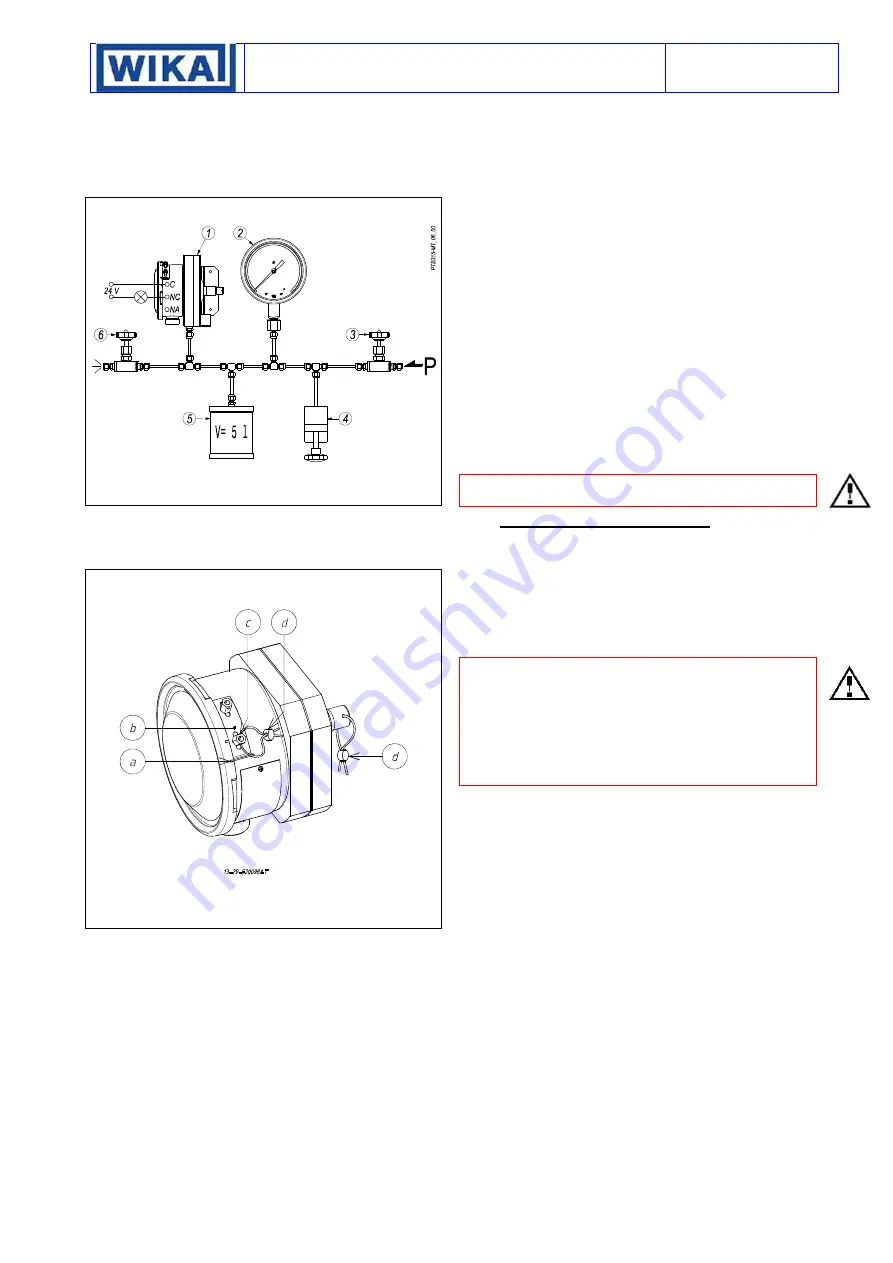
Fig. 3 – Calibration circuit for instrument with adjustable range less
than 60 mbar
1- Pressure switch
2- Test
gauge
3- Inlet valve
4- Volumetric
pump
5- Capacity
6- Outlet
valve
6.1 PRELIMINARY
OPERATIONS
Remove the blocking device fixed to the side of the instrument
case (Fig. 4). Remove the cover by rotating it in an anticlockwise
direction.
Fig. 4 - Pressure switch blocking device
a) Blocking
gap
b) Blocking
bracket
c) Blocking
nut
d) Plumbing
wire
6.2 CALIBRATION CIRCUIT AND OPERATIONS
Prepare the calibration circuit as indicated in Fig.3.
The warning lamps should be connected to contact in the NO or
NC position according to the required contact action.
Connection of C and NO terminals
• If the circuit is open at the working pressure, the switch
closes
the circuit as the pressure
increases
when the desired value is
reached.
• If the circuit is closed at the working pressure, the switch
opens
the circuit as the pressure
decreases
when the desired value is
reached.
Connection of C and NC terminals
•
If the circuit is closed at the working pressure, the switch
opens
the circuit as the pressure
increases
when the desired value is
reached.
• If the circuit is open at the working pressure, the switch
closes
the circuit as the pressure
decreases
when the desired value is
reached.
The pressure switch must be mounted in the normal installation
position, i.e. with the pressure connection pointing downwards.
The pressure conn (or H) of the instrument must be
connected to the pressure source and the connection - (or L) has
to be left to the atmosphere
Increase the pressure in the circuit up to the desired set point
value for the first microswitch. Use a wide bladed screwdriver, as
indicated on the label, turn the screw until the relative lamp turns
on (or turns off).
6.3 CHECK OF SET POINT
Generate the normal working pressure and wait the pressure
stabilisation. Vary the pressure into the circuit and record the set
point value. Write the set point values on the adhesive label.
Note
: the repeatability should be checked verifying for three
times the set point (Pi) starting always from the same pressure
value (Pw). The pressure cycle should be slowly to give the
possibility to record the set point with enough accuracy.
6.4 FINAL
OPERATIONS
Disconnect the instrument from the calibration circuit.
Take the cover, ensure that the sealing gasket is correctly fitted
into its seat, and insert the cover onto the case, with the blocking
gap positioned in correspondence to the blocking bracket.
Turn the cover clockwise closing it tightly. Mount the blocking
device as in Fig. 4.
Mount on pressure connection, cable entry and adjustment screw
the protection caps supplied with the instrument.
Caution:
The protection caps should only be definitively
removed
during
the connection steps.
7
MOUNTING AND CONNECTIONS
7.1 MOUNTING
Surface
mount the instrument by means of the holes provided,
(see Fig.10 and 11). In case of surface or panel or rack mounting
the instruments can be mounted side by side (see Fig.12 & 13).
The chosen position must be such that vibrations, the possibility
of shocks or temperature changes are within tolerable limits. The
instrument
must
be positioned higher than the pipe inlet (Fig.14).
7.2 PRESSURE
CONNECTIONS
Connecting lines are an integral part of the instrument in
transmitting the measured variable from the measuring point to
the instrument.
The diameter and length of the two connecting lines between
instrument and pressure taps are to be such as not to cause
dampening or lag in transmitting the differential pressure.
Run connecting lines always sloping down from instrument to
process so that possible condensate flows towards process
(avoid forming of siphons).
For a correct installation (see Fig 14) it is necessary to:
Mount
a shut-off valve with drain (root valve) on each process
pipe inlet to allow the instrument to be excluded and the
connection tubing to be drained. It is recommended that said
valve has a capstan blocking device aimed at preventing it being
activated casually and without authorisation.
Mount
a
3 valve manifold
near the instrument to permit possible
functional verification on site and removal of the instrument. It is
recommended that the manifold is made up of two service valves,
one by-pass valve and two suitably connected drain plugs. The
three valves with the drains can be reunited by a single device
called a “Three valve manifold”
Mount
a three piece joint onto the threaded attachment of the
instrument to permit the easy mounting or removal of the
instrument itself.
Carry out
the connection using a flexible tube in such a way that
variations in the temperature of the tube itself do not force the
instrument attachment.
Ensure
that all the pressure connections are airtight. It is
important that there are no leakage in the circuit.
Close root valves, the two service valves, drain plugs and open
the by-pass valve.


