


14033590.01 10/2014 GB/D
WIKA operating instructions model CS4S
11
GB
Display
Description
(1) PV
Actual value display
The actual value (PV = process variable) is displayed with a red LED display.
(2) SV
Set point display
The set point (SV = setting value) or the manipulated variable (MV) is displayed with a
green LED display.
(3) SV1
Set point 1
The green LED lights up when set point 1 (SV1) is activated.
(4) SV2
Set point 2
The yellow LED lights up when set point 2 (SV2) is activated.
(5) OUT1
Control output 1
The green LED lights up when control output 1 is ON.
(When the control output is analogue current signal, the LED blinks in proportion to the
output power.)
(6) OUT2
Control output 2
The yellow LED lights up when control output 2 is ON.
(7) A1
Alarm output 1 (A1)
The red LED lights up when alarm output 1 is ON.
(8) EVT
Event display
The red LED lights up when the event output is ON (Option [2Ax]: Alarm output 2 and/
or option [W1x] heater burnout alarm).
(9) AT
Auto tuning
The yellow LED blinks when the auto tuning or the auto reset function is activated.
(10) TX/RX
TX/RX display
The yellow LED lights up when serial interface is active.
Key
Description
(11) ▲
Up key
Increases a numerical value or selects a setting parameter.
(12) ▼
Down key
Reduces a numerical value or selects a setting parameter.
(13) MODE
MODE key
Selects the setting mode and stores the selected setting parameter.
(14)
OUT
/
OFF
OUT
/
OFF
key
Depending on the setting in the menu of the “Function
OUT
/
OFF
key”, using this key,
the controller is switched off or switched to manual control (see chapters 7.6 and 7.7)
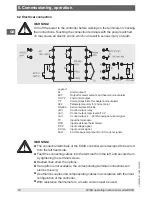
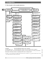
When the settings for this controller must be set, first link connection terminals
1 and 2 for the power supply, then follow the setting in accordance with
chapter 7 “Configuration”, before moving on to chapter 6 “Commissioning,
operation”.
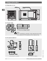
4. Design and function