INSTALLATION · MANUAL
2
/4
WIBRE Elektrogeräte Edmund Breuninger GmbH & Co. KG · Liebigstrasse 9 · 74211 Leingarten/Germany
Telefon: +49 (0) 7131 9053-0 · Telefax: +49 (0) 7131 9053-19 · E-Mail: [email protected]
3. Installation des Einbaugehäuse
(4.0299.00.00) bei einer Neuinstallation und
Montage der Befestigungselemente
ACHTUNG:
Bei einer Installation in vorhandene Einbaugehäuse
(4.0274) bitte Hinweise ab Punkt 4 beachten!
Zur Installation sind die nationalen Sicherheitsvorschriften zu
beachten. Es wird keine Haftung für unsach gemäßen Einsatz oder
Montage übernommen. Bei nachträglichen Änderungen an den
Leuchten wird keine Haftung übernommen.
3.1 Einbau in Betonbecken (Eingießen in Beton) mit Fliesen-
auskleidung
Die Schutzfolie auf dem Einbautopf nicht beschädigen und erst
bei Installation der Innenteile entfernen! Kon takt mit Baustahl ist
zu vermeiden! Das Einbaugehäuse einmessen (Teilkreis 204 mm)
und laut em pfoh lener Einbautiefe mit den zwei beiliegenden
Kunststoffschrauben M6x60 so an der Verschalung befes ti gen,
dass die Leitungsverschraubung 45° seitlich versetzt ist und die
Gewindebuchsen horizontal/vertikal aus gerichtet sind. (siehe
3.1
)
Kabelschutzschlauch am Einbautopf anschellen und möglichst über
den Was serspiegel und in großem Radius verlegen. Nach Entfernen
der Verschalung bis an den Innenrand des Ein bautopfes anfliesen,
Schutzfolie entfernen.
3.2 Einbau in Betonbecken mit Folienauskleidung (feste Folie)
mittels Druckflansch
Der Einbau des Einbautopfes entspricht dem Einbau in Betonbecken.
Die auf dem Einbautopf aufgebrachte Schutzfolie vor Einlegen der
Beckenfolie entfernen!
Nachdem die Beckenfolie eingelegt ist, werden die erforderlichen
Öffnungen für Schein werfer (ø182 mm) und den Lochungen (ø7
mm) für die V4A-Schrauben M6x30 ausgeschnitten. Der Edelstahl-
druckflansch (4.0274.00.25) kann hier als Schablone verwendet wer-
den. Der Edelstahldruckflansch wird mit den Schrauben V4A M6x30,
Flachdichtung, Beckenfolie, Flachdichtung (Reihen folge beachten) in
den Gewindebuchsen am Einbau topf fest verschraubt.
Achtung:
Flachdichtungen laut Grafik verwenden, die Becken-
folie muss unbedingt zwischen den beiden Flachdichtungen des
Edelstahldruckflansches (4.0274.00.25) liegen.
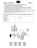
14 mm
3.6
Mörtel/mortar
Fliesen/tiles
Kunststoffwinkelring/
plastic adapter ring
Scheinwerfer/spotlight
V4A-Schraube M6x10/
V4A-screw M6x10
Kunststoffbefestigungsring/
plastic fastening ring
V4A-Schraube M6x20/
V4A-screw M6x20
Dichtung/seal
3.0
1
3
4
6
5
2
1. Scheinwerfer/spotlight 4.0299
2. Einbautopf/installation housing
4.0299.00.00
3. 2x Schraube/screw M6x40
oder/or M6x80 V4A
4. Kabelverschraubung komplett/
cable gland complete PG13,5
5. Befestigungsbügel
Edelstahl/fastening ring steel
(9.0299.00.10)
6. Spezial-Unterwasserkabel/
special underwater cable
3.1
Betonwand/
concrete wall
Mörtel/mortar
Fliesen/tiles
Scheinwerfer/
spotlight
3.2
Flachdichtung/
flat seal
Flachdichtung/flat seal
Beckenfolie/
pool liner foil
Edelstahl-Druckflansch/
stainless steel
pressure flange
V4A-Schraube M6x30
V4A-screw M6x30
Kunststoffformscheibe/
plastic shaped washer
Scheinwerfer/
spotlight
3.3
Kunststoffformscheibe/
plastic shaped washer
Edelstahl-Druckflansch/
stainless steel
pressure flange
Flachdichtung/
flat seal
Flachdichtung/
flat seal
Beckenwand/
pool wall
V4A-Schraube M6x30
V4A-screw M6x30
Scheinwerfer/
spotlight
3.4
dichtgeschweißt
IP68/welded IP68
V4A-Blech/
V4A-wall
Scheinwerfer/
spotlight
3.5
Klebefolie/
adhesive foil
Klebeflansch/
adhesive flange
Flachdichtung/
flat seal
Scheinwerfer/
spotlight
Fliesenaufbau optimal 14 mm!/Tile+mortar optimum 14 mm!
3. Installation of the installation housing
(4.0299.00.00) in a new installation and
mounting of the fastening elements
NOTE:
When installing in an existing installation housing
(4.0274), please follow the instructions from point 4!
National safety regulations must be followed during installation. No
liability will be accepted for improper use or mounting. No liability will be
accepted in case of subsequent changes to the lights.
3.1 Installation in concrete basins (in poured concrete) with tile
covering
Do not damage the protective foil on the built-in housing and remove it
only when installing the internal parts! Avoid contact with structural steel!
Measure the installation housing (arc 204 mm) and fasten it to the shea-
thing at the recommended installation depth with the two accompanying
M6x60 plastic screws so that the line fitting is laterally offset 45° and the
threaded bushings are oriented horizontally/vertically. (see
3.1
) Clamp
cable conduit to the built-in housing and emplace it, if possible, above the
water surface and in a large radius. After removing the sheathing, tile up to
the inside edge of the built-in housing and remove protective foil.
3.2 Installation in concrete basin with foil lining (firm foil) using
pressure flanges
Installation of the built-in housing corresponds to installation in concrete
basins. Remove the protective foil attached to the built-in housing before
emplacing the basin foil!
After the basin foil is installed, the required openings for spotlights (ø182
mm) and the holes (ø7 mm) for the V4A screws M6x30 are cut out. The
stainless steel pressure flange (4.0274.00.25) can be used as a pattern
here. The stainless steel pressure flange is firmly screwed into the built-in
housing with screws V4A M6x30, gasket, basin foil and gasket (observe
sequence) in the threaded bushings.
Note:
Use gaskets in accordance with the figure; the basin foil
must always lie between the two gaskets of the stainless steel
pressure flange (4.0274.00.25).
3. Installation d‘un boîtier d‘encastrement
(4.0299.00.00) en cas de nouvelle installation
et montage des éléments de fixation
ATTENTION :
en cas d‘installation dans un boîtier d‘encastrement
(4.0274) existant, respecter les instructions à partir du point 4 !
Respecter les prescriptions de sécurité nationales pour l‘installation. Toute
responsabilité pour l‘utilisation et le montage incorrect est déclinée. Toute
responsabilité est déclinée pour les modifications ultérieures sur les lampes.
3.1 Intégration dans des dalles en béton (scellement) à revête-
ment de carrelage
Ne pas endommager le film de protection sur le boîtier d‘encastrement et ne
l‘enlever que lors de l‘installation des éléments intérieurs ! Éviter tout contact
avec l‘acier de construction ! Mesurer le boîtier d‘encastrement (section circulaire
de 204 mm) et le fixer au coffrage conformément à la profondeur de montage
recommandée avec deux vis pour plastique M6x60 de manière à ce que le
raccord à vis du câblage soit décalé de 45° sur le côté et que les douilles filetées
sont alignées à l‘horizontale/la verticale. (voir
3.1
) Fixer la gaine de protection
des câbles au boîtier d‘encastrement à l‘aide d‘un collier et la poser, si possible,
au-dessus du niveau d‘eau et en respectant un grand rayon. Après avoir retiré
le coffrage, carreler jusqu‘au bord intérieur du boîtier d‘encastrement et retirer
le film de protection.
3.2 Intégration dans les dalles en béton avec habillage de film
(film fixe) au moyen d‘un bride de pression
L‘intégration du boîtier d‘encastrement est identique à l‘intégration dans
des dalles en béton. Retirer le film de protection appliqué sur le boîtier
d‘encastrement avant la mise en place du liner du bassin.
Après avoir posé le liner du bassin, découper les ouvertures requises pour le
projecteur (ø182 mm) et les trous (ø7 mm) pour les vis V4A M6x30. La bride de
pression en acier inoxydable (4.0274.00.25) peut être utilisée comme gabarit.
Visser fermement la bride de pression en acier inoxydable avec les vis V4A
M6x30, les joints plats, le liner de bassin, le joint plat (respecter l‘ordre) dans les
douilles filetées du boîtier d‘encastrement.
Attention:
utiliser les joints plats conformément à l‘illustration,
le liner de bassin doit impérativement être placé entre les deux joints
plats de la bride de pression en acier inoxydable (4.0274.00.25).