background image

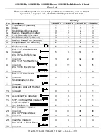
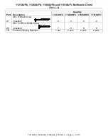
1121AUFb, 1126AUFb, 1180AUFb and 1181AUFc McKenzie Chest 

Assembly Instructions


1121AUFb_1126AUFb_1180AUFb_1181AUFc 

— Page 4 — 07/13 

Tool Required: Phillips Screwdriver


1. 

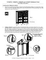
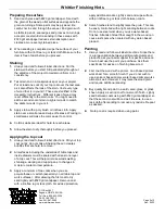
Place the unit at its final destination. Rotate the Small Adjustable Glides (Y) found at the corners 
of the unit and the Adjustable Glide with Hex Nut (YA) at the bottom of the Assembled Foot (YB) 
until the unit is level. See Figure 1. 


2. 

Tipping restraint: 

Locate the stud(s) in the wall behind the unit. Attach a Clip (T1) to one wall 

stud with two #8 x 2" Black Screws (T3). See Figure 2a. Attach a second clip to the unit with two 
#6 x 5/8" Philtruss Screws (T5). See Figure 2b. Connect the two clips with the Nylon Restraint 
Strap (T2). Pull the Nylon Restraint Strap (T2) tight so there is no slack. See Figures 2c and 2d. 
Repeat this procedure to attach the second tipping restraint. If you cannot locate two studs, 
purchase the proper wall attachment hardware for your type of wall and secure the unit. 

Fig. 1 

YB 

(1181 shown) 

YA 

Fig. 2a 

T1 

T3 

Pull tight 

Fig. 2d 

(1181 shown) 

T1 

T2 

T

Fig. 2c 

Pull the Nylon Restraint 

Strap (T2) tight  

so there is no slack. 

T

T5 

T1 

Fig. 2b 

Summary of Contents for McKenzie 1121AUFb

Page 1: ...iture be sure to find and properly install the tipping restraint s If you cannot locate the restraint s please contact us immediately for replacement Notice to California Customers California Prop 65 requires consumer goods to be labeled if any one of 850 different chemicals or substances including wood dust is present even in trace amounts Drilling sawing sanding or machining wood products genera...

Page 2: ...3 2 2 3 J Medium Drawer Face attached 0 2 2 4 K Large Drawer Face attached 2 1 2 4 L Knob attached 5 8 10 11 Q 8 x 1 1 2 Machine Screw installed 5 8 10 11 T 8 x 7 8 Lo Profile Screw inserted 20 26 32 60 U 8 x 1 1 4 Pan Head Screw inserted 3 12 12 21 V 8 x 1 3 16 Black Screw inserted 0 0 0 6 W 8 x 1 1 4 Black Screw inserted 0 0 0 5 Y Small Adjustable Glide installed 4 4 4 4 YA Adjustable Glide with...

Page 3: ...s List 1121AUFb_1126AUFb_1180AUFb_1181AUFc Page 3 07 13 Part Description Quantity 1121AUFb 1126AUFb 1180AUFb 1181AUFc ZT 8 x 2 Black Screw inserted 0 0 0 2 ZU 8 x 1 3 8 Lo Profile Screw inserted 7 8 8 9 TR Furniture Tipping Restraint 1 set 2 sets 2 sets 2 sets ...

Page 4: ...e unit Attach a Clip T1 to one wall stud with two 8 x 2 Black Screws T3 See Figure 2a Attach a second clip to the unit with two 6 x 5 8 Philtruss Screws T5 See Figure 2b Connect the two clips with the Nylon Restraint Strap T2 Pull the Nylon Restraint Strap T2 tight so there is no slack See Figures 2c and 2d Repeat this procedure to attach the second tipping restraint If you cannot locate two studs...

Page 5: ... Assembly Instructions for detailed information on how to glue your specific product Use wood glue such as Elmer s Wood Glue Titebond Wood Glue or the equivalent Some instructions call for a slow drying epoxy glue Carefully read the label and instructions of the glue manufacturer Your unit may not need glue 1 We strongly recommend that you lay out all the parts and familiarize yourself with how th...

Page 6: ...follow all label directions Stir your top coat gently do not shake Shaking the can creates bubbles that are hard to remove 2 All surfaces including the underside of table tops and inside drawers must be sealed with at least one layer of a top coat This will help minimize wood swelling shrinkage warping and cupping due to changes in moisture content or temperature 3 Apply a minimum of two coats whe...

Reviews: