16
Parking Brake Adjustment
WARNING:
Never attempt to adjust the
brakes while the engine is running. Always
disengage PTO, move speed control lever
into neutral position, stop engine and remove
key to prevent unintended starting.
If the tractor does not come to a complete stop when
the brake pedal is completely depressed, or if the
tractor’s rear wheels can roll with the parking brake
applied (and the hydrostatic bypass rod pulled out), the
brake is in need of adjustment. The brake disc can be
found on the right side of the transmission in the rear of
the tractor. Adjust if necessary as follows:
NOTE:
A replacement cotter pin (part no. 714-0111)
is needed to complete this adjustment. Have one on
hand before proceeding.
•
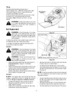
Looking at the transmission from the right side of
the tractor, locate the compression spring and
brake disc. See Figure 11.
•
Carefully remove the cotter pin from the crown nut
on the right side of the brake assembly.
•
Using a feeler gauge, check the gap between the
brake disc and the brake puck. Proper gap is .011".
•
Tighten the crown nut until the proper gap is
achieved.
•
Insert the replacement cotter pin into the crown nut.
Steering Adjustment
If the tractor turns tighter in one direction than the other,
or if either the tie rod and ferrule are being replaced due
to damage or wear, the tie rod may need to be adjusted.
To do so, proceed as follows:
NOTE:
A replacement cotter pin (part no. 714-0470)
is needed to complete this adjustment. Have one on
hand before proceeding.
•
Place the steering wheel in position for straight
ahead travel.
•
In front of the pivot bar, measure the distance
horizontally from the inside of the left rim to the
inside of the right rim. Note the distance.
•
Behind the pivot bar, measure the distance
horizontally from the inside of the left rim to the
inside of the right rim. Note the distance.
•
The measurement taken in front of the pivot bar
should be between 1/16” and 5/16” less than the
measurement taken behind the pivot bar. If it is not,
an adjustment is necessary. Proceed as follows.
•
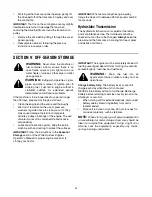
Locate the ferrule at the right end of the tie rod, just
to the rear of the right, front tire of tractor. See
Figure 12.
Figure 11
Figure 12
•
Remove the cotter pin and flat washer which
secures the adjustment ferrule to the tractors right-
hand axle.
•
Two turns at a time, thread the adjustment ferrule
toward the right, front tire to lengthen the tie rod.
Or, thread the adjustment ferrule away from the
right, front tire to shorten the tie rod.
NOTE:
Lengthening the tie rod increases the tractor’s
front tie toe-in. Shortening the tie rod decreases the
tractor’s front tire toe-in.
•
Reinsert the adjustment ferrule and temporarily
secure it with the cotter pin removed earlier.
•
Make certain the steering wheel is in position for
straight-ahead travel before again taking
measurements. Continue to repeat the steps above
until a proper adjustment is achieved.
Crown Nut
NOTE:
Rear, right wheel not shown for clarity
Brake Disc
Tie Rod
Ferrule
Right-hand Axle
Flat Washer,
Right Front Tire
Cotter Pin


