background image

1INSTALLATION

The dryer is designed for installation using a flexible gas
connection with tubing in accordance with B.S.669.
Ensure that the supply gas sizing is adequate.
When installing, position the appliance so that the plug is
accessible.
An electric supply cord with moulded-on 13 Amp.plug is
fitted at the back of the dryer.The length is 1.5 m.(5ft.).
If there are any other appliances that are relatively high
rated (eg a central heating boiler)fed from the same gas
supply branch, it is advisable to perform the verification of
inlet pressure with both appliances in operation.
Prior to installation, check that the local distribution
conditions, nature of gas and pressure and adjustment of
the dryer are compatible.

2 AIR SUPPLY

The tumble dryer shall be installed in a room or internal
space having an openable window, or equivalent.The
customer must be advised that this must be kept open
during use.

Purpose provided ventilation of 100cm² shall also be 
provided where the room volume is less than 3.7m 3/kw 
of appliance rated heat input.
Additional guidance on the provision of air supply may be
obtained from BS5440 parts 1 and 2 and BS 7624:2004
If the dryer is to be installed in a room or internal space 
that already contains one or more fuel burning 
appliances, the ventilation requirements above, together 
with any additional requirements of BS5440-2:2009, 5,5 
shall be applied.

3 POSITION

The dryer must not be installed in a bedroom, bathroom 
or shower room.
Great care is required in the location of the dryer in
premises where concentrations of flammable vapours 
may accumulate, e.g.commercial garages and associated
workshops.
The dryer can be placed against a wall, other appliances,
kitchen furniture and similar surfaces.

4 VENTING 

The dryer must be fitted with an exhaust vent hose and 
the end either hung out of a window or fitted to a wall/ 
window vent connection.

Note: 

Do not obstruct or add a mesh to the vent hose

outlet during use and ensure that it cannot be blocked or 
bent sharply which obstructs the air flow.
It is recommended that the interior of the hose be
periodically inspected and cleaned if necessary.

PERMANENT VENTING

Accessory wall/window vent kit CL005 is available:
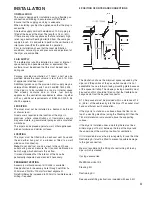
See illustration for necessary hole through wall.Dim A=
200mm and Dim B= 100mm for direct alignment.
Note DimBmay be increased to 200mm to facilitate easier
drilling if required.

5 POSITION OF DRYER AND CONNECTIONS

The illustration shows the minimum space required by the
dryer and the position of the gas wall connector.It is not
acceptable to use a forward facing mounting plate because
of the space limitation.The sideways facing assembly must
be used and this should be fitted so that the flexible hose
hangs down from the bayonet connector.

A 13 Amp socket must be provided within a distance of 1.4
m (55 in.) of the cable entry into the dryer.The socket must
have an efficient earth connection.

If the dryer is to stand on a surface above the floor or on
top of a washing machine (using the Stacking Kit) then the
750 mm dimension is measured above the supporting
surface.

If the dryer is installed under a worktop there must be a
minimum gap of 15 mm between the top of the dryer and
the underside of the worktop to allow for ventilation.

If it is intended to move the dryer regularly for use then the
Restraining Kit must be fitted to prevent possible damage
to the gas connection.

We also recommend the fitting of a restraining kit to any
dryer which is stacked.

If using accessories:

Wall/Window Vent Kit 

Stacking Kit 

Restraining Kit 

See separate fitting instructions included with each Kit.

INSTALLATION  

4

Summary of Contents for eco 86A

Page 1: ...stallation and Use Regulations 2009 Guidance may be obtained from the relevant parts of B S 7624 B S 5440 parts 1 and 2 B S 6891 current editions I E E Wiring Regulations and relevant Building Regulations Failure to install the appliance correctly could invalidate the warranty liability claims and could lead to prosecution FOR USE IN THE UNITED KINGDOM AND IRELAND WITH NATURAL GAS ONLY I2H GAS SUP...

Page 2: ...5 EC EN60335 1 EN60335 2 11 GAS APPLIANCE DIRECTIVE GAS GAD 2009 142 EC BS EN 1458 1 EN 1458 1 2000 ELECTROMAGNETIC COMPATIBILITY DIRECTIVE 2004 108 EC EN55014 EN 61000 3 2 EN 61000 3 3 EN 62233 2 WARNING THIS APPLIANCE SHALL BE INSTALLED IN ACCORDANCE WITH THE LOCAL REGULATIONS IN FORCE AND ONLY IN A WELL VENTILATED SPACE READ THE INSTRUCTIONS BEFORE USING OR INSTALLING THIS APPLIANCE ...

Page 3: ... C BURNER Pressed steel with slotted flame perforations Heat input 3 0kW 10235 Btu hr Injector 1 32 mm dia 3 CONTROL Type Pactrol full sequence flame control Ignition electrode gap to burner 3 to 4mm Flame failure electrode 4213 078 52641 Height from heater base to centre of electrode 27 0 0 5mm INLET THERMOSTAT Brown wires identification Bi metal contacts normally closed Contacts open if airflow ...

Page 4: ...urniture and similar surfaces 4 VENTING The dryer must be fitted with an exhaust vent hose and the end either hung out of a window or fitted to a wall window vent connection Note Do not obstruct or add a mesh to the vent hose outlet during use and ensure that it cannot be blocked or bent sharply which obstructs the air flow It is recommended that the interior of the hose be periodically inspected ...

Page 5: ...lord s gas safety certificate If you do have any maintenance activity carried out it should be carried out by a competent person i e registered Engineer 9 STACKING Instructions for stacking if required are supplied with the stacking kit PROGRAMME The electronic control measures dryness by the electrical resistance method and operates relays to a energise the drive motor in foward and reverse rotat...

Page 6: ...orce to disconnect the bayonet fitting between the Fan Access Cover 447 and the back of the Banjo Assy 440 From underneath the dryer withdraw the 4 screws 396 securing the Motor Bracket 432 to the cabinet base Lift out the Motor and Fan Assy Special tool 7813 002 61111 is recommended when installing a new belt which needs to be levered and stretched onto the motor spindle see illustration A capaci...

Page 7: ... Bearing Assy 270 to the Back Panel 24 Withdraw the 8 screws securing the Back Panel 24 to the Cabinet 196 Disengage the T piece Grommet from the slot in the Back Panel and lift off The Rear Seal 14 can be prised off the inside of the Back Panel 24 with a screw driver but care should be taken not to damage the inner sheet metal flange Remove excess adhesive before fitting the replacement Rear Sear...

Page 8: ......

Page 9: ......

Page 10: ... 232 352 211 552 235 372 213 377 233 353 218 217 219 249 ...

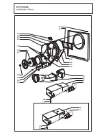
Page 11: ...ECO 86A_ 15 16 17 393 375 38 389 375 18 375 20 23 21 22 412 375 19 403 396 24 25 26 27 25 14 13 143 398 28 141 408 409 410 411 144 Exploded View 2 ...

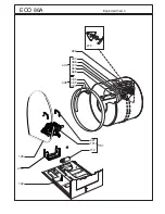
Page 12: ...32 31 406 13 248 440 442 441 445 446 447 448 356 250 229 406 13 32 29 30 31 456 458 459 445 454 455 ECO 86A_ EXPLODED VIEW 3 ...

Page 13: ...ECO 86A Exploded View 4 466 477 444 467 465 463 468 464 438 439 266 270 ...

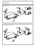
Page 14: ...ECO 86A Exploded View 5 375 39 41 33 482 411 45 1 31 406 13 Exploded View 5 1 Heater Assembly 375 39 41 33 482 411 45 31 13 ...

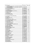
Page 15: ...092 08521 3 30 Exhaust Tube 4213 077 48013 3 31 4 Way Housing Assembly 4213 092 08431 3 5 33 Flame Failure Electrode 4213 092 19801 5 38 Inlet Thermostat Inlet Temperature Limiter 4213 092 33911 2 39 Ignition Electrode 4213 092 08491 5 41 M4 x 10 Pan Screw 2522 180 40002 5 45 Solenoid Coil SCEM 4213 092 08501 5 45 1 Solenoid Coil 4213 092 64541 5 101 Motor and Capacitor Assembly 4213 092 25611 4 1...

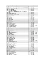
Page 16: ...386 Table Top Assembly Ellipse 4213 092 46211 1 387 Cable Tie 4213 077 41772 1 389 Screw 6AB x 6 5 2522 165 20003 2 393 Flex Support Clip 4213 077 40982 2 394 Foot 4213 077 39833 1 396 Flb Ear Scr St Zn 8 x 3 8 8213 130 38051 1 2 3 398 Screw M4 x 25 2522 180 40003 2 4 403 Roller Assembly 4213 092 35651 2 406 M5 Toothed Lockwasher 2513 611 01008 3 407 Hex Nut DC St Zn M5 2522 401 55012 1 2 408 Cabl...

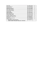
Page 17: ... 465 Slip Ring 4213 075 13141 4 466 Ring Spring 4213 075 70931 4 467 Sensing Strip 4213 075 13152 4 468 Sensing Strip Clip 4213 077 41176 4 477 Ring Spring Plug 4213 074 81353 4 482 M4 Toothed Lockwasher 2522 616 15007 5 537 W Button access cover 4213 078 26311 3 552 Neon 4213 089 96911 1 555 Rear Panels Seal Kit 4213 092 28001 2 556 HT Lead 4213 176 00771 1 Bearing Pads Brush Seal Kit 4213 092 21...

Page 18: ......

Page 19: ......

Page 20: ...Manufactured By Crosslee plc Halifax Road Halifax W Yorks HX3 8DE 4213 194 05463 ...

Reviews: