


INSTALLATION
18
June 2021 W-SQ-Pro 15 and W-SQ-Pro 18
Realise that people are not used to having
230/400 Volt available on a vehicle. Put
warning signs on wall sockets and on
junction boxes. Instruct non-regular users
of the vehicle. Warn maintenance personal
of garages that do service on the vehicle.
Generators used on mobile/land
applications that are operated in a
hazardous environment have often to fulfil
special regulations and additional
measures have to be taken accordingly.
Be sure that all electrical installations (including all safety
systems) comply with all required regulations of the local
authorities. All electrical safety/shutdown and circuit
breaking systems have to be installed onboard as the
generating set itself cannot be equipped with such
equipment for every possible variation.
The vehicle’s power supply system should be suitable and
safe for the AC voltage which is applied and the power that
will be generated. Special attention has to be paid on
dividing the system in branches which are fused
individually.
It is absolutely essential that each and every circuit in the
electrical system is properly installed by a qualified
electrician.
The AC wiring of the W-SQ- PRO 15/10.8 – three phase
and the Whisper 16 Ultra – three phase can be arranged as
STAR configuration (230 / 400 V AC / 50 Hz) or a DELTA
configuration (230 V AC / 50 Hz)
When connected as a STAR configuration, 3x 400 Volt is
available between the phases. At the same time 230 Volt is
available between every phase and neutral. When
connected as a DELTA configuration 3x 230 Volt is
available between the phases. See chapter 4 for electrical
wiring diagrams.
When applying 3 phases the installation should be laid out
in such a way that there is a reasonable balance of load
between the three phases. The AC wiring of the W-SQ-Pro
18/15 single phase and the W-SQ-Pro 15/11 single phase
is arranged as series connection (230 V AC / 50 Hz). In
single phase only 1x 230 Volt is available between the
phase and neutral.
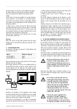
1
FUSE
The generating set are fitted with an integrated circuit
breaker. The current rating of this circuit breaker depends
on the generator type, see the table below for more details.
Model
Maximum output current
W-SQ- PRO 15
1phase/3phase
1 x 59 Amp / 3 x 20 Amp
W-SQ- PRO 18
1phase/3phase
1 x 76 Amp / 3 x 25 Amp
Output fuses and insulation guards (between the generating
set and the electrical installation) should be installed to
protect the installed electrical system. For electrical motors
connected to the system, a motor protection switch must be
installed.
2
GROUNDING
The AC alternator windings are not grounded.
The housing of the alternator and all other metal parts are
grounded.
To make a connection between “neutral” and “ground” is
necessary as part of a specific insulation failure protection
system.
It is possible that the electric installation in the vehicle must
be protected against insulation failures. Methods of
protection are subjected to rules that can be different
depending on the use of the vehicle and local standards.
Experts in this field should be consulted.
3
CABLE
For the power cable we recommend the use of 3 wire cable
for single phase or 5 wire cable for 3 phase. The cable
should be oil resistant and have a sufficient cross sectional
area. One wire of the cable should be used for earth. For
long cables it is recommended to apply cables with a larger
cross section (refer to ISO 13297 annex A)
4
TRANSFER SWITCH
A power source selector switch can be installed between
the generating set and the vehicle’s electrical supply
system. This switch must ensure that all AC consumers can
be switched off at once. This switch should also be installed
to keep the generating set and shore (grid) power systems
separate.
Transfer switches - to switch over from a land line to vehicle
or from generating set to inverter - should be well designed
to switch over all wires including neutral (and not only
phases or line) and there should be provisions with the aid
of timers to prevent relays from clattering.
WARNING
In all situations the transfer switches
between shore, inverter and generator
should switch all connections, the phase
lines (L1, L2, L3) as well as neutral (N).


