background image

Part Identification

Hardware Identification

Hardware Usage Guide

Assembly Steps

Français

Español

Safety

Warranty

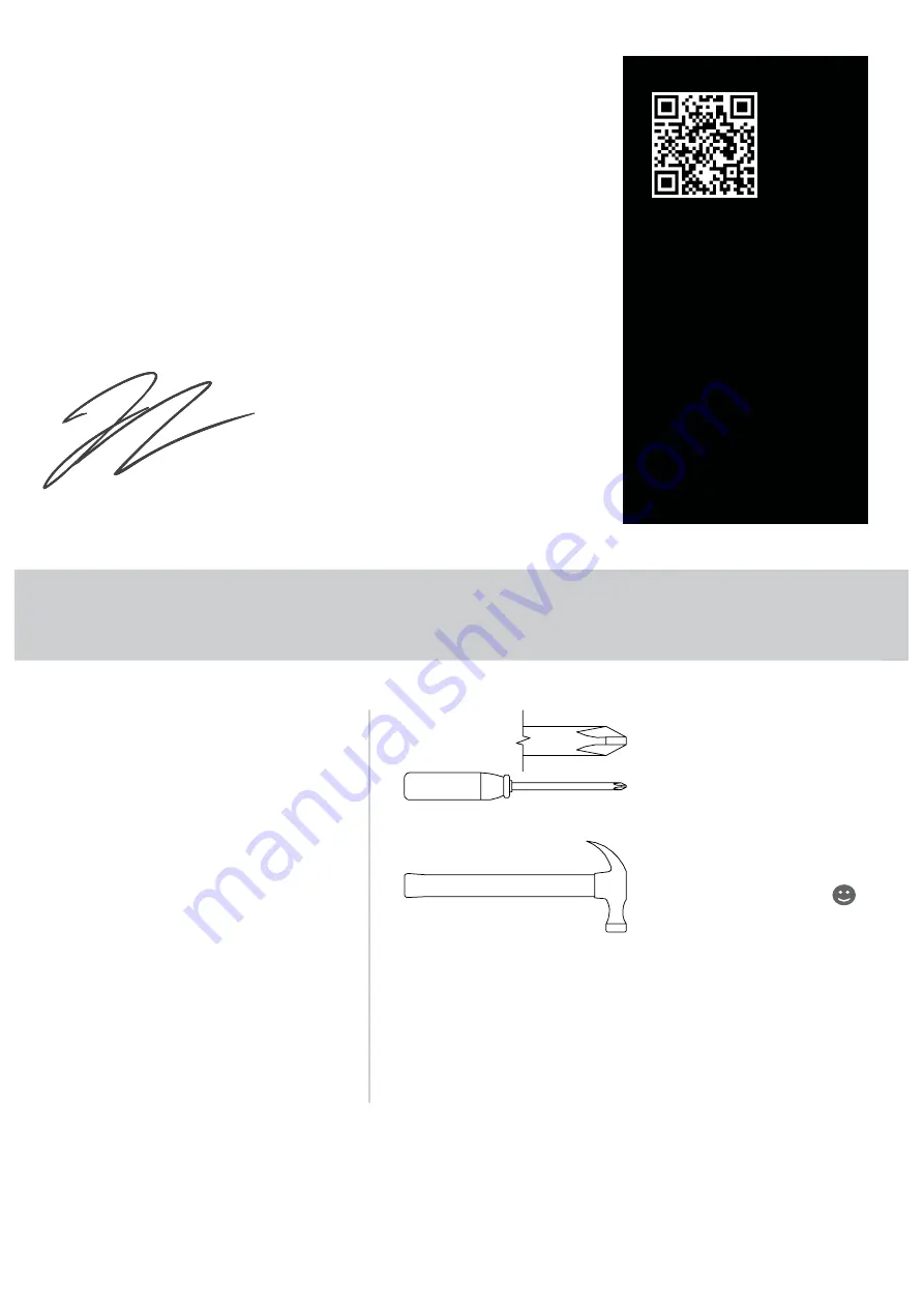
Hammer

Not actual size   

No. 2 Phillips Screwdriver

Tip Shown Actual Size

ASSEMBLY TOOLS REQUIRED

TABLE OF CONTENTS

THANK YOU FOR PURCHASING THE BARRISTER DOG CRATE!

I am thrilled that Whisker and Sauder furniture have partnered 
together to bring you the highest-quality pet furniture. At 

Whisker, we design and deliver refined pet accessories that 

delight both pets and people. Whisker and Sauder products  
are made with environmentally responsible materials and  
world-class manufacturing processes. Together, our companies 
are bringing pet parents a premium line of stylish yet functional 
pet furniture that is built to last. Enjoy!

Jacob Zuppke, President of Whisker

3

4-5

6

7-30

31-35

36-40

41-42

43

429421

whiskersupport.com

Page 2

REGISTER YOUR NEW 

PRODUCT ONLINE

For immediate service, 
our website is available 24 
hours per day, 7 days per 
week, to order replacement 
parts, access assembly tips,  
register your product and 
view Sauder products.

www.sauder.com/service

Summary of Contents for SAUDER BARRISTER 429421

Page 1: ...placement part please contact Sauder directly at www sauder com or 800 445 1527 Customer Service is available Monday Friday 9 a m to 5 30 p m EST except holidays WHISKER BARRISTER DOG CRATE support whisker com 1 877 250 7729 Mon Fri 9am 5pm EST ...

Page 2: ...d pet accessories that delight both pets and people Whisker and Sauder products are made with environmentally responsible materials and world class manufacturing processes Together our companies are bringing pet parents a premium line of stylish yet functional pet furniture that is built to last Enjoy Jacob Zuppke President of Whisker 3 4 5 6 7 30 31 35 36 40 41 42 43 429421 whiskersupport com Pag...

Page 3: ...entify similar parts Now you know our ABCs PART IDENTIFICATION A TOP 1 B SHELF 1 C BOTTOM 1 D UPPER BACK 1 E LOWER BACK 1 F LEFT END 1 G RIGHT END 1 H BOTTOM MOLDING 1 J DOOR 2 K FOOT 1 L CUSHION 1 M DRAWER FRONT 1 N DRAWER BACK 1 O LEFT DRAWER SIDE 1 P RIGHT DRAWER SIDE 1 Q DRAWER BRACE 1 R DRAWER BOTTOM 1 S UPRIGHT 1 A B C D E F G H J L M N O P Q R S K J 429421 whiskersupport com Page 3 ...

Page 4: ...N CAM 21 3 1 EXTENSION RAIL 2 2 EXTENSION SLIDE 2 EXTENSION SET SHOWN SEPARATED CAM SCREW 21 4 LARGE WOOD DOWEL 28 5 SMALL WOOD DOWEL 2 6 7 BUSHING 4 8 GROMMET 1 9 PULL 1 10 LATCH SET 2 11 PIVOT HINGE 4 FELT DISC CARD 1 12 L WRENCH 1 15 USB POWER HUB 1 14 APPLIQUE CARD 1 13 429421 whiskersupport com Page 4 ...

Page 5: ... your unit 16 2 HEX HEAD SCREW 1 17 2 PAN HEAD SCREW 2 18 1 9 16 PAN HEAD SCREW 5 19 1 3 16 FLAT HEAD SCREW 4 22 9 16 FLAT HEAD SCREW 8 23 1 2 FLAT HEAD SCREW 24 20 13 16 MACHINE SCREW 2 21 9 16 MACHINE SCREW 4 429421 whiskersupport com Page 5 HARDWARE IDENTIFICATION ...

Page 6: ...y tap the CAM DOWEL until the shoulder is against the surface of the part 1 3 Insert the CAM SCREW or CAM DOWEL into the HIDDEN CAM Tighten the HIDDEN CAM 1 2 2 Arrow Push a HIDDEN CAM into the part The arrow in the HIDDEN CAM must point toward the hole in the edge of the board Hole Hidden Cam HARDWARE USAGE GUIDE 429421 whiskersupport com Page 6 ...

Page 7: ...ssemble your unit on a carpeted floor or on the empty carton to avoid scratching your unit or the floor å Fasten two BUSHINGS 7 to both sides of the UPRIGHT S as shown Use two 9 16 MACHINE SCREWS 21 429421 whiskersupport com Page 7 F L I P OVER 7 S S 9 16 MACHINE SCREW 2 used in this step 21 Go on spoil em a little ...

Page 8: ... å Fasten the BOTTOM C to the BOTTOM MOLDING H Use three 1 9 16 PAN HEAD SCREWS 18 å NOTE You should start each SCREW a few turns before completely tightening any of them å NOTE Be sure the WOOD DOWELS in the MOLDING insert into the BOTTOM STEP 2 429421 whiskersupport com Page 8 3 Arrow Arrow 3 C H C Surface with HIDDEN CAMS 5 1 9 16 PAN HEAD SCREW 3 used in this step 18 ...

Page 9: ... two 1 9 16 PAN HEAD SCREWS 18 å NOTE You should start each SCREW a few turns before completely tightening any of them å NOTE Be sure the WOOD DOWEL in the SHELF inserts into the UPRIGHT STEP 3 429421 whiskersupport com Page 9 5 3 Arrow Arrow 3 B Surface with HIDDEN CAMS B 1 9 16 PAN HEAD SCREW 2 used in this step 18 Finished edge S ...

Page 10: ...å Fasten the BOTTOM C to the UPRIGHT S Use one 2 PAN HEAD SCREW 17 STEP 4 429421 whiskersupport com Page 10 S C Surface with HIDDEN CAMS 2 PAN HEAD SCREW 1 used in this step 17 H ...

Page 11: ...three LARGE WOOD DOWELS 5 into the edge of the UPPER BACK D å Push the LOWER BACK E onto the WOOD DOWELS in the UPPER BACK D å Insert the GROMMET 8 into the large hole in the UPPER BACK D STEP 5 429421 whiskersupport com Page 11 3 Arrow Arrow 3 3 Arrow 5 E D 8 ...

Page 12: ... BACK E å Fasten the BOTTOM C to the LOWER BACK E Use one 2 PAN HEAD SCREW 17 å NOTE Be sure the WOOD DOWELS in the BACK insert into the BOTTOM STEP 6 429421 whiskersupport com Page 12 5 C E 2 PAN HEAD SCREW 1 used in this step 17 NOTE With someone s help carefully lift the assembly onto the BACKS ...

Page 13: ... G å Push two HIDDEN CAMS 3 into the RIGHT END G å Fasten one BUSHING 7 to the RIGHT END G Use one 9 16 MACHINE SCREW 21 STEP 7 429421 whiskersupport com Page 13 4 Arrow 3 7 9 16 MACHINE SCREW 1 used in this step 21 G The large hole must be here ...

Page 14: ...23 å NOTE For each EXTENSION RAIL turn a SCREW into the 1st hole shown in the diagram Then slide the inner cartridge of the EXTENSION RAIL in to find the other holes that line up with the holes in the END Turn a SCREW into each hole å NOTE The EXTENSION SLIDES will be used later for the DRAWER 1 2 Open end Push the black lever and pull the SLIDE from the RAIL G The large hole must be here 1 1 2 FL...

Page 15: ...the RIGHT END G to the SHELF B BOTTOM C and LOWER BACK E Tighten five HIDDEN CAMS å NOTE Be sure the WOOD DOWELS in the END insert into the SHELF BOTTOM and both BACKS STEP 9 429421 whiskersupport com Page 15 5 7 used B C E G Hey It s starting to look like something ...

Page 16: ...t com Page 16 å Turn five CAM SCREWS 4 into the LEFT END F å Push two HIDDEN CAMS 3 into the LEFT END F å Fasten one BUSHING 7 to the LEFT END F Use one 9 16 MACHINE SCREW 21 4 7 9 16 MACHINE SCREW 1 used in this step 21 F Arrow 3 ...

Page 17: ...turn a SCREW into the 1st hole shown in the diagram Then slide the inner cartridge of the EXTENSION RAIL in to find the other holes that line up with the holes in the END Turn a SCREW into each hole STEP 11 429421 whiskersupport com Page 17 F Open end 1 1st 1 1st 1 2 FLAT HEAD SCREW 3 used in this step 23 Open end ...

Page 18: ...Insert seven LARGE WOOD DOWELS 5 into the LEFT END F å Fasten the LEFT END F to the SHELF B BOTTOM C and LOWER BACK E Tighten five HIDDEN CAMS å NOTE Be sure the WOOD DOWELS in the END insert into the SHELF BOTTOM and both BACKS 5 7 used B C E F ...

Page 19: ...C Tighten one 2 HEX HEAD SCREW 16 using the L WRENCH 15 å Peel FELT DISCS from the FELT DISC CARD 12 and stick them onto the FOOT K and each LEG STEP 13 429421 whiskersupport com Page 19 15 K C 2 HEX HEAD SCREW 1 used in this step 16 12 ...

Page 20: ...x LARGE WOOD DOWELS 5 into the TOP A å Fasten the TOP A to the UPPER BACK D and ENDS F and G Tighten five HIDDEN CAMS å NOTE Be sure the WOOD DOWELS in the TOP insert into the BACK and ENDS STEP 14 429421 whiskersupport com Page 20 4 F G A A D 5 6 used ...

Page 21: ... 9 16 FLAT HEAD SCREWS 22 å Fasten two PIVOT HINGES 11 to the LEFT sides of the DOORS J Use six 1 2 FLAT HEAD SCREWS 23 STEP 15 429421 whiskersupport com Page 21 Post 1 2 FLAT HEAD SCREW 6 used for the HINGES 23 11 10 J J 9 16 FLAT HEAD SCREW 4 used for the LATCHES 22 ...

Page 22: ...to the tracks in the RIGHT END G and UPRIGHT S å NOTE The PIVOT HINGES will hang down å Fasten the CATCHES from the LATCH SETS 10 to the BOTTOM C Use four 9 16 FLAT HEAD SCREWS 22 STEP 16 429421 whiskersupport com Page 22 11 10 9 16 FLAT HEAD SCREW 4 used in this step 22 C Post S G ...

Page 23: ...PRIGHT S to the RIGHT side of the DOOR J as shown Use three 1 2 FLAT HEAD SCREWS 23 å Repeat this step for the other DOOR using the PIVOT HINGE in the RIGHT END G STEP 17 429421 whiskersupport com Page 23 J S 1 2 FLAT HEAD SCREW 6 used for the HINGES 23 G ...

Page 24: ...through the hole in the RIGHT END G and out through the hole in the UPPER BACK D å The USB PORT END will snugly insert into the hole in the RIGHT END G Place the POWER PLUG back onto the USB END if needed STEP 18 429421 whiskersupport com Page 24 G 14 D Power plug USB port end USB end ...

Page 25: ...WER FRONT M and DRAWER BACK N å Push six HIDDEN CAMS 3 into the DRAWER SIDES O and P and DRAWER BRACE Q STEP 19 429421 whiskersupport com Page 25 3 Arrow Arrow 3 4 Q P O N M If you re doing this to help a friend don t leave without a bite ...

Page 26: ...htening any of them å Insert one SMALL WOOD DOWEL 6 into the DRAWER BACK N å Fasten the DRAWER BRACE Q to the DRAWER BACK N Tighten one HIDDEN CAM å NOTE Be sure the WOOD DOWEL in the DRAWER BACK inserts into the DRAWER BRACE STEP 20 429421 whiskersupport com Page 26 Q O P N O P 6 Surface with HIDDEN CAMS 1 3 16 FLAT HEAD SCREW 4 used in this step 19 Groove N ...

Page 27: ...FRONT M å Fasten the DRAWER FRONT M to the DRAWER SIDES O and P and DRAWER BRACE Q Tighten five HIDDEN CAMS å NOTE Be sure the WOOD DOWEL in the DRAWER FRONT inserts into the DRAWER BRACE STEP 21 429421 whiskersupport com Page 27 6 Unfinished surface N O P Q O P M R NOTE Be sure the DRAWER BOTTOM inserts into the groove in the DRAWER FRONT ...

Page 28: ... 1 2 FLAT HEAD SCREWS 23 å Fasten one PULL 9 to the DRAWER FRONT M Use two 13 16 MACHINE SCREWS 20 STEP 22 429421 whiskersupport com Page 28 2 1 2 FLAT HEAD SCREW 6 used for the SLIDES 23 Open end Open end Open end 2 2 9 M P O 13 16 MACHINE SCREW 2 used for the PULL 20 ...

Page 29: ...he EXTENSION RAILS on the unit and push the drawer into the unit until the drawer is fully inserted The drawer will push in hard until it is all the way in then it will slide in and out easier å Insert the CUSHION L into the bottom of your unit STEP 23 429421 whiskersupport com Page 29 L ...

Page 30: ...ER SIDES O and P å NOTE Please read the back pages of the instruction booklet for important safety information å This completes assembly Clean with a damp cloth Wipe dry STEP 24 429421 whiskersupport com Page 30 P O 13 15 lbs 50 lbs And to celebrate why not share your success story at whisker com or ...

Page 31: ... correspond à la même étape en anglais Comparer la Liste de pièces ci dessous avec la PART IDENTIFICATION du manuel en anglais pour vous familiariser avec les pièces avant l assemblage REMARQUE CE MANUEL D INSTRUCTIONS CONTIENT D IMPORTANTES INFORMATIONS RELATIVES À LA SÉCURITÉ À LIRE ET CONSERVER POUR TOUTE RÉFÉRENCE FUTURE CAISSE POUR CHIEN WHISKER BARRISTER ENSEMBLE DE GLISSIÈRE ILLUSTRÉ À PART...

Page 32: ... élément sur un sol à moquette ou sur le carton vide pour éviter d endommager l élément ou le sol Fixer deux MANCHONS 7 aux les deux côtés du MONTANT S comme l indique le schéma Utiliser deux VIS À MÉTAUX 14 mm 21 ÉTAPE 2 Enfoncer quatre EXCENTRIQUES ESCAMOTABLES 3 dans le DESSOUS C REMARQUE S assurer de bien insérer les EXCENTRIQUES ESCAMOTABLES complètement dans les trous Insérer deux GRANDES CH...

Page 33: ...ENSION 2 des GLISSIÈRES D EXTENSION 1 comme l indique le schéma ci dessous supérieure Faire attention car les pièces sont graissées Fixer une GLISSIÈRE D EXTENSION 1 à l EXTRÉMITÉ DROITE G Utiliser trois VIS TÊTE PLATE 13 mm 23 REMARQUE Pour chaque GLISSIÈRE D EXTENSION faire tourner une VIS dans le premier trou indiqué dans le schéma Ensuite enfiler la cartouche interne de la GLISSIÈRE D EXTENSIO...

Page 34: ...ans le DESSUS A Insérer six GRANDES CHEVILLES EN BOIS 5 dans le DESSUS A Fixer le DESSUS A à l ARRIÈRE SUPÉRIEUR D et aux ARRIÈRES F et G Serrer cinq EXCENTRIQUES ESCAMOTABLES REMARQUE S assurer d insérer les CHEVILLES EN BOIS du DESSUS dans l ARRIÈRE et les EXTRÉMITÉS ÉTAPE 15 Fixer les LOQUETS des ENSEMBLES DE LOQUETS 10 aux PORTES J Utiliser quatre VIS TÊTE PLATE 14 mm 22 Fixer deux CHARNIÈRES ...

Page 35: ...es pages arrière du manuel d instructions Ceci complète l assemblage Nettoyer avec un tissu humide Essuyer ÉTAPE 21 Enfiler le FOND DE TIROIR R dans les rainures des CÔTÉS DE TIROIR O et P et de l ARRIÈRE DE TIROIR N Insérer une PETITE CHEVILLE EN BOIS 6 dans le DEVANT DE TIROIR M Fixer le DEVANT DE TIROIR M aux CÔTÉS DE TIROIR O et P et à l ENTRETOISE DE TIROIR Q Serrer cinq EXCENTRIQUES ESCAMOTA...

Page 36: ...dentification en el folleto en inglés para familiarizarse con Las partes de ensamblaje NOTA ESTE FOLLETO DE INSTRUCCIONES CONTIENE INFORMACIÓN IMPORTANTE SOBRE LA SEGURIDAD POR FAVOR LEA Y GUÁRDELO PARA REFERENCIA EN EL FUTURO 7 BUJE 4 8 OJAL 1 9 TIRADOR 1 10 CONJUNTO DE PESTILLO 2 11 BISAGRA DE PIVOTE 4 12 TARJETA CON TOPES DE FIELTRO 1 13 TARJETA CON APLICACIONES 1 14 CONCENTRADOR DE ENERGÍA USB...

Page 37: ... EXCÉNTRICO O PASADOR DE EXCÉNTRICO NOTA Varias BIELAS DE EXCÉNTRICO o un PASADOR DE EXCÉNTRICO pueden ser utilizados 1 Gire una BIELA DE EXCÉNTRICO o ligeramente golpee el PASADOR DE EXCÉNTRICO hasta que el resalto repose contra de la parte 2 Empuje un EXCÉNTRICO ESCONDIDO dentro de la parte La flecha en el EXCÉNTRICO ESCONDIDO debe apuntar hacia el agujero en el borde de la tabla 3 Inserte la BI...

Page 38: ... BIELAS DE EXCÉNTRICO 4 en el EXTREMO DERECHO G Empuje dos EXCÉNTRICOS ESCONDIDOS 3 en el EXTREMO DERECHO G Fije un FORRO 7 al EXTREMO DERECHO G Utilice un TORNILLO PARA METAL de 14 mm 21 PASO 8 Separe las CORREDERAS DE EXTENSIÓN 2 de los RIELES DE EXTENSIÓN 1 como se muestra en el diagrama superior más abajo Prepárese las piezas son grasientas Fije un RIEL DE EXTENSIÓN 1 al EXTREMO DERECHO G Util...

Page 39: ... LLAVE EN L 15 Separe los TOPES DE FIELTRO de la TARJETA CON TOPES DE FIELTRO 12 y aplique los sobre cada PATA K y cada PIERNA PASO 14 Atornille cinco BIELAS DE EXCÉNTRICO 4 dentro del PANEL SUPERIOR A Inserte seis PASADORES DE MADERA GRANDES 5 en el PANEL SUPERIOR A Fije el PANEL SUPERIOR A al DORSO SUPERIOR D y a los EXTREMOS F y G Apriete cinco EXCÉNTRICOS ESCONDIDOS NOTA Asegúrese de que los P...

Page 40: ... páginas de atrás del folleto de instrucciones en cuanto a importante información de seguridad Esto completa el ensamblaje Limpiar con un trapo húmedo Seque con un paño PASO 20 Fije los LADOS DE CAJÓN O y P al DORSO DE CAJÓN N Utilice cuatro TORNILLOS DE CABEZA PERDIDA de 30 mm 19 NOTA Debe apretar cada TORNILLO unas vueltas antes de apretar cualquier tornillo firmemente Inserte un PASADOR DE MADE...

Page 41: ... mobilier à bon escient et avec prudence Une mauvaise utilisation peut être à l origine de risques d accident ou peut endommager le mobilier et les articles ménagers Lire attentivement le tableau suivant À surveiller Danger éventuel Solution Les enfants qui grimpent sur le mobilier Un enfant peut grimper sur le mobilier pour essayer d attraper un jouet animaux domestiques ou tout autre objet Risqu...

Page 42: ...tes alimentos etc encima de las unidades de mobiliario El mal uso del mobiliario para soportar televisores Es peligroso colocar televisores sobre unidades no diseñadas para soportarlos Riesgo de lesiones o la muerte Los televisores pueden ser muy pesados El peso y la ubicación del tubo de imagen tienden a causar la inestabilidad de televisores y por eso tendrán la tendencia a inclinarse hacia adel...

Page 43: ...de rechange seront garanties uniquement pendant la période restante de la garantie originale SAUDER NE SERA EN AUCUN CAS RESPONSABLE de TOUT DOMMAGE ACCESSOIRE OU CONSÉCUTIF DE TOUTE SORTE et lesdits dommages sont EXCLUS DE LA PRÉSENTE GARANTIE à savoir perte d utilisation démontage transport main d œuvre ou dommages matériels sur ou à proximité du produit Certains États ou provinces ne permettant...

Page 44: ...with the CPSC Ban on Lead Containing Paint 16 CFR 1303 3 This product is manufactured for Sauder Woodworking Company 502 Middle St Archbold OH 43502 419 446 2711 4 Date of Manufacture __________________________ IF YOU NEED ASSISTANCE PLEASE CONTACT OUR MICHIGAN BASED CUSTOMER SERVICE TEAM support whisker com 1 877 250 7729 Mon Fri 9am 5pm EST except holidays WHISKERSUPPORT COM August 2021 ...

Reviews: