
22
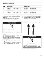
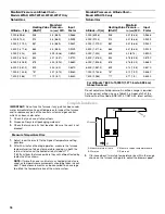
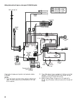
Wiring Connection Diagram—Honeywell
®
VR 8205 System
G
W
BK
W (NEUT)
R (LO)
OR (MED/LO)
BU (MED)
Y (MED/HI)
BK (HIGH)
Y
Y/BK Stripe
W
BK/W Stripe
OR
GY
R
BU
BK
W
Line Voltage - Factory
Line Voltage - Field
Low Voltage - Factory
Low Voltage - Field
Thermostat & Sub-base
Heat Anticipator
0.60 Amp
Condenser
Aux
Limit
Switch
Aux
Limit
Switch
If Used
Blower Off
Delay Timing
(See Note 3)
Pressure
Switch
High Limit
Switch
Fault Code
History
Button
(See Note 1)
Rollout
Switch
Rollout
Switch
If Used
Transformer
Induced
Draft
Blower
Hot Surface Igniter
Interlock
Switch
Circulation
Blower
Not on all models
Gas Control
Valve
Flame
Sensor
OR
MV
MV
V
V
V
W
BR
PARK
PARK
PARK
5A Fuse
NEUTRALS
Y
W
Y
BK
60
90
120
180
R C W Y G
TWIN
SW1
60
90
120
180
OR
HUM
L1
XFMR
CONT
EA
C
COOL
HEA
T
V
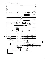
Check codes for proper wiring and circuit protection before
installation.
NOTES:
1. Press and release fault code history button to display fault
codes. To erase codes, press and hold button in for more
than 5 seconds.
2. If any of the original wire as supplied with the furnace must be
replaced, it must be replaced with wiring material having a
temperature rating of at least 194ºF (90ºC).
3. Blower off delay timing is factory set at 120 seconds. To
change, move the jumper to the pins adjacent to the desired
setting.


