background image

12

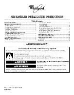
Wiring Diagram - Electric Heat and Blower

15 Amp

Supply

Voltage

L1

L2 OR

N

Wiring Diagram: No Heat

Wire Nuts

By Others

14 G

2

14 BK

1

    To 

Ground Lug

14 Y (240V)

14 W (120V)

6-Pin

 Plug

18 R

18 BU

14 R

18 BK

18 G

18 BU

4

BR

6

2

5

3

1

TR

14 BK

240V

18 BU

208V

COM

24V

14 BK L1

14 Y L2

BK

18 R

18 G

R

G

18 W

18 BU

C

W1

To

Thermostat

By Others

R

G

W

BU

W2

CAP = Motor Capacitor

GND = Ground Connection

MTR = Blower Motor

BR = Blower Relay

TD = Time Delay (Opt.)

TR = Transformer

SEQ = Sequencer

CB = Circuit Breaker

GND = Ground Lug

LS = Limit Switch

HE = Heater Element

Wiring Diagram - Electric Heat

Control Circuit Wiring To

Be 24 Volt, N.E.C. Class 2 

Power (Factory Wired)

Power (Field Wired)

Control (Factory Wired)

Control (Field Wired)

Plug Pin

Location

(Opt.)

Amp 350781-1

6-Pin Cap

4

1

5

6

2

3

TB = Terminal Block

(Opt.)

Heaters Used

5 KW = HE1

7.5 & 10 KW = HE1 & HE2

15 KW = HE1,HE2 & HE3

20 KW = HE1,HE2,HE3 & HE4

24

C

3

2

6

5

1

4

W (IF 120V)

GND

BR

BR/W

3

4

R

BK

MTR

Cap

1

Y

14 BK (HI)

14 Y (COM)

2

14 R (LO)

Part No. 065866900

Line Voltage

by Others

TD

H

H

12 BK

12 BK

5

6

1

2

3

4

To Blower

Ground Lug

14 BK

14 Y

1

2

18 BU

14 G

4

18 W

5

L2A

L1A

CB1

GND

12 BK

12 BK

3

5

4

1

SEQ1

14 R

3

Plug

6-Pin

12 Y

12 Y

12 BK

LS2

LS1

HE2

HE1

12 BK

1st Stage

6

OR

220V

+

**

+

**

120V

CB2

SEQ2

18 BU

5

3

4

1

12 Y

LS4

HE4

LS3

12 BK

HE3

12 Y

12 BK

GND.

L1B

L2B

2nd Stage

18 BK

Summary of Contents for WAHM

Page 1: ...mplete Installation 12 SEQUENCE OF OPERATION 14 AIR HANDLER MAINTENANCE 14 ASSISTANCE OR SERVICE 14 Accessories 14 WARRANTY 15 Whirlpool Models WAHU WAHM 065937400 You can be killed or seriously injured if you don t immediately You can be killed or seriously injured if you don t follow All safety messages will tell you what the potential hazard is tell you how to reduce the chance of injury and te...

Page 2: ...nd follow the instructions provided with any tools listed here Tools Needed Parts Needed Check local codes check existing electrical supply and read Ductwork Requirements and Electrical Requirements before purchasing parts OutdoorSystemRequirements The air handler is designed to match and must be used with outdoor units as rated The indoor sections are manufactured with an interchangeable refriger...

Page 3: ...pply Adequate support must be provided to ensure cabinet integrity Ensure that there is adequate room to remove service and access panels if installing in the horizontal position For correct horizontal coil installation see Installation Configuration Options later in this section IMPORTANT This coil is provided with a secondary drain that should be trapped and piped to a location that will give th...

Page 4: ... drain pan and the side drain pan 5 Remove the side drain pan from the coil drain pan assembly and install on the opposite side 6 Reinstall the coil drain pan assembly in the same orientation as before by lifting and sliding into the air handler 7 Install the coil support bracket on the opposite side of the air handler A Drain connections B Coil access cover C Blower access cover A Drain connectio...

Page 5: ...E Use copper conductors only All field wiring must be done in accordance with National Electrical Code applicable requirements of UL and local codes where applicable Electrical wiring disconnect means and over current protection are to be supplied by the installer Refer to the air handler rating plate for maximum over current protection minimum circuit ampacity as well as operating voltage The pow...

Page 6: ...ension of the blower housing and minimizes air expansion losses from the blower INSTALLATION INSTRUCTIONS InspectShipment These air handlers are completely factory assembled and all components are performance tested Each unit consists of a blower assembly refrigerant coil and controls in an insulated galvanized steel factory finished enclosure Knockouts are provided for electrical wiring entrance ...

Page 7: ...ow complete drainage of the pan NOTE Horizontal runs must also have an anti siphon air vent standpipe installed ahead of the horizontal run See Typical Condensate Drain Connection in this section An extremely long horizontal run may require an oversized drain line to eliminate air trapping Typical Condensate Drain Connection secondary drain not shown NOTE Do not operate air handler without a drain...

Page 8: ...ions are ready to be completed 1 Route the suction and liquid lines from the fittings on the indoor coil to the fittings on the outdoor unit Run the lines in as direct a path as possible avoiding unnecessary turns and bends 2 Make sure that the suction line is insulated over the entire exposed length and that both suction and liquid lines are not in direct contact with floors walls ductwork floor ...

Page 9: ... with electrical power 1 2 or 3 circuits See the air handler Accessory Kit label for number of circuits and ratings 2 Disconnect all power supplies 3 Knock out the correct number of knockouts 1 2 or 3 and install UL listed wires and fittings A Connect yellow to yellow B Connect black to black C Connect ground wire to ground terminal marked GND WARNING Electrical Shock Hazard Electrically ground ai...

Page 10: ...nnects are used the front panel knockouts will need to be removed 8 Reinstall the air handler blower access panel 9 Reconnect power 10 Dispose of recycle all remaining parts WARNING Electrical Shock Hazard Electrically ground electric heater Connect ground wire to ground terminal marked GND Use copper wire rated for supply connection Correct wire gauge is shown in the chart below Failure to follow...

Page 11: ...Only Application Thermostat Air Handler Air Handler Air Handler Thermostat Thermostat R R R G G G BU BU W W W Heat Pump Unit BK BK Cooling Application with Electric Heat Heat Pump Application with Electric Heat Condensing Unit Connect common wire only if required See thermostat installation instructions ...

Page 12: ...ng Diagram Electric Heat Control Circuit Wiring To Be 24 Volt N E C Class 2 Power Factory Wired Power Field Wired Control Factory Wired Control Field Wired Plug Pin Location Opt Amp 350781 1 6 Pin Cap 4 1 5 6 2 3 TB Terminal Block Opt Heaters Used 5 KW HE1 7 5 10 KW HE1 HE2 15 KW HE1 HE2 HE3 20 KW HE1 HE2 HE3 HE4 24 C 3 2 6 5 1 4 W IF 120V GND BR BR W 3 4 R BK MTR Cap 1 Y 14 BK HI 14 Y COM 2 14 R ...

Page 13: ... matches the maximum cooling capacity rating of the air handler If the outdoor unit is smaller than the maximum cooling capacity rating for the air handler the cooling blower speed may need to be changed Refer to Blower Performance Chart IMPORTANT The cooling blower speed must be set to provide a minimum of 350 CFM airflow per ton 12 000 Btu h of outdoor cooling capacity To change blower speed Ref...

Page 14: ...position the heat pump will be locked out of the heating circuit and all heating will be electric heat if applicable A jumper should be placed between W 2 and E on the thermostat subbase so that the electric heat control will transfer to the first stage heat on the thermostat This will allow the indoor blower to cycle on and off with the electric heat when the fan switch is in the AUTO position AI...

Page 15: ...15 ...

Page 16: ...late Dealer name____________________________________________________ Address ________________________________________________________ Phone number__________________________________________________ Model number __________________________________________________ Serial number __________________________________________________ Installation date ________________________________________________ 0659374...

Reviews: