


8
Install Microwave Oven
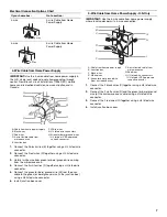
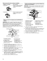
1. Using 2 or more people, lift the microwave oven partially into
the cabinet cutout above the spacer bars. Place the
microwave oven on top of the spacer bars and to the outside
of the guide flanges.
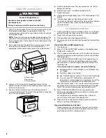
NOTE: Open the microwave oven door and push against the
seal area of the microwave oven front frame when pushing
the microwave oven into the cabinet. Do not push against the
outside edges.
2. Push against the front frame of the microwave oven to push
the oven into the cabinet. Push the microwave oven
completely into the cabinet and center in the cabinet cutout.
3. Using a
¹⁄₈
" (3.2 mm) drill bit, predrill pilot holes into the
cabinet through the holes in the mounting rails on each side
of the microwave oven.
4. Securely fasten microwave oven to cabinet using the 2
screws provided. Insert the screws through holes in mounting
rails. Do not overtighten screws.
5. Reattach the bottom vent that was removed in the “Install
Spacer Kit” section.
6. Replace oven racks, turntable and support hub.
7. Reconnect power.
8. Display panel will light briefly, and “PF” should appear in the
display.
9. If display panel does not light, please reference the
“Assistance or Service” section of the Use and Care Guide or
contact the dealer from whom you purchased your
microwave oven.
Complete Installation
1. Check that all parts are now installed. If there is an extra part,
go back through the steps to see which step was skipped.
2. Check that you have all of your tools.
3. Dispose of/recycle all packaging materials.
4. For microwave oven use and cleaning, read the Use and Care
Guide.
Check Operation of Microwave Oven
1. Turn power on.
2. When “CLOCK ENTER TIME” appears in the display, press
START/ADD A MINUTE.
3. Fill a microwave-safe container with 1 cup (250 mL) of water
and place container inside microwave oven on the turntable.
Close door firmly.
4. Touch START/ADD A MINUTE twice to set cooking time to
“2:00” minutes. Microwave should begin cooking, interior
light should be on, and the display should count down the
remaining time.
If microwave does not operate, check the following:
■
Household fuse is intact and tight; or circuit breaker has
not tripped.
■
Electrical supply is connected;
■
See “Troubleshooting” section in the Use and Care Guide.
■
If an error code (“F” followed by a number plus “E”
followed by a number) appears in the display, turn off the
microwave oven and contact a qualified technician.
When the display reads “1:00” minute, open the microwave
oven door. The microwave should stop cooking. Close door
firmly. The interior microwave oven light should turn off.
5. Press START/ADD A MINUTE to resume preset cycle.
Microwave should begin cooking, and the microwave oven
interior light should be on.
Let microwave oven complete cooking time. A tone will
sound 3 times at the end of the cooking time.
6. Open microwave oven door and slowly remove container.
Water in container should be hot.
If you need Assistance or Service:
Please reference the “Assistance or Service” section of the
Use and Care Guide or contact the dealer from whom you
purchased your built-in microwave oven.
A. Guide flange
B. Spacer bar
C. Microwave oven
A. Two screws
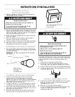
WARNING
Excessive Weight Hazard
Use two or more people to move and install
microwave oven.
Failure to do so can result in back or other injury.
C
B
A
C
A