Whirlpool W10355490A Installation Instructions Manual Download Page 3

3

INSTALLATION REQUIREMENTS

Tools and Parts

Gather the required tools and parts before starting installation. 
Read and follow the instructions provided with any tools listed 
here.

Tools needed

Phillips screwdriver

Measuring tape

Level

Drill

¹⁄₈

" (3.2 mm) drill bit 

Parts needed

A UL listed or CSA approved conduit connector

UL listed wire connectors

Parts supplied

Check local codes. Check existing electrical supply. See 
“Electrical Requirements.”

It is recommended that all electrical connections be made by a 
licensed, qualified electrical installer.

Location Requirements

IMPORTANT: Observe all governing codes and ordinances. 

Cabinet opening dimensions that are shown must be used. 
Given dimensions provide minimum clearance with 
microwave oven.

Recessed installation area must provide complete enclosure 
around the recessed portion of the microwave oven. 

Grounded electrical supply is required. See “Electrical 
Requirements” section.

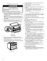
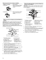
Electrical supply junction box should be located 3" (7.6 cm) 
maximum below the support surface when the microwave 
oven is installed in a wall cabinet. A 1" (2.5 cm) minimum 
diameter hole should have been drilled in the right rear or left 
rear corner of the support surface to pass the appliance cable 
through to the junction box.

NOTE: For undercounter installations, it is recommended that 
the junction box be located in the adjacent right or left 
cabinet. If you are installing the junction box on the rear wall 
behind the microwave oven, the junction box must be 
recessed and located in the upper or lower right or left corner 
of the cabinet. Otherwise, the microwave oven will not fit into 
the cabinet opening.

For installation above single built-in oven the junction box 
must be located inside upper cabinet.

If you are installing the junction box on rear wall behind the 
microwave oven, the junction box must be recessed and 
located in the upper or lower right or left corner of the cabinet; 
otherwise, the microwave oven will not fit into the cabinet 
opening.

Microwave oven support surface must be solid, level and flush 
with bottom of cabinet cutout. Floor must be able to support a 
weight of 110 lbs (50.0 kg).

IMPORTANT: To avoid damage to your cabinets, check with your 
builder or cabinet supplier to make sure that the materials used 
will not discolor, delaminate or sustain other damage. This oven 
has been designed in accordance with the requirements of UL 
and CSA International and complies with the maximum allowable 
wood cabinet temperatures of 194°F (90°C).
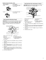
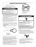
A. Spacer bars (2)
B. Bottom vent (1)

C. Phillips head screws (2)
D. ¾" pan head screws (4)

A

B

C

D

A

Summary of Contents for W10355490A

Page 1: ... INSTALLATION INSTRUCTIONS 6 Prepare Built In Microwave Oven 6 Assemble Spacer Kit 6 Install Spacer Kit 6 Make Electrical Connection 6 Install Microwave Oven 8 Complete Installation 8 SÉCURITÉ DU FOUR À MICRO ONDES ENCASTRÉ 9 EXIGENCES D INSTALLATION 10 Outils et pièces 10 Exigences d emplacement 10 Spécifications électriques 12 INSTRUCTIONS D INSTALLATION 13 Préparation du four à micro ondes enca...

Page 2: ...n if the instructions are not followed Your safety and the safety of others are very important We have provided many important safety messages in this manual and on your appliance Always read and obey all safety messages This is the safety alert symbol This symbol alerts you to potential hazards that can kill or hurt you and others All safety messages will follow the safety alert symbol and either...

Page 3: ... surface to pass the appliance cable through to the junction box NOTE For undercounter installations it is recommended that the junction box be located in the adjacent right or left cabinet If you are installing the junction box on the rear wall behind the microwave oven the junction box must be recessed and located in the upper or lower right or left corner of the cabinet Otherwise the microwave ...

Page 4: ...m overall width D 22 57 0 cm max recessed depth E 17 45 1 cm recessed height including spacers 27 68 6 cm models A 27 68 6 cm min cabinet width B 1 2 5 cm top of cutout to bottom of upper cabinet door C 40 101 2 cm bottom of cutout to floor recommended D 25 64 8 cm cutout width E 1 3 8 cm min bottom of cutout to top of cabinet door F 19 49 4 cm cutout height 30 76 2 cm models A 30 76 2 cm min cabi...

Page 5: ...rowave oven frame When a 4 wire single phase 208 220 volt 60 Hz AC only electrical supply is required a 20 amp maximum circuit protection is required fused on both sides of the line A time delay fuse or circuit breaker is recommended Connect directly to the fused disconnect or circuit breaker box through flexible nonmetallic sheathed copper cable with grounding wire See Make Electrical Connection ...

Page 6: ...ace using four pan head screws provided Do not overtighten the screws 4 Remove the bottom vent bottom vent will be reattached after the microwave oven is installed Make Electrical Connection This microwave oven is manufactured with a neutral white power supply wire and a cabinet connected green or bare ground wire twisted together 1 Disconnect power 2 Feed the flexible cable conduit from the micro...

Page 7: ... Use the 3 wire cable from home power supply where local codes permit a 3 wire connection 1 Connect the 2 black wires C together using a UL listed wire connector 2 Connect the 2 white wires D and the green or bare ground wire of the microwave oven cable using a UL listed wire connector 3 Connect the 2 red wires G together using a UL listed wire connector 4 Install junction box cover If your home h...

Page 8: ... cleaning read the Use and Care Guide Check Operation of Microwave Oven 1 Turn power on 2 When CLOCK ENTER TIME appears in the display press START ADD A MINUTE 3 Fill a microwave safe container with 1 cup 250 mL of water and place container inside microwave oven on the turntable Close door firmly 4 Touch START ADD A MINUTE twice to set cooking time to 2 00 minutes Microwave should begin cooking in...

Page 9: ... cas de non respect des instructions Votre sécurité et celle des autres est très importante Nous donnons de nombreux messages de sécurité importants dans ce manuel et sur votre appareil ménager Assurez vous de toujours lire tous les messages de sécurité et de vous y conformer AVERTISSEMENT DANGER Voici le symbole d alerte de sécurité Ce symbole d alerte de sécurité vous signale les dangers potenti...

Page 10: ...n de l appareil jusqu au boîtier de connexion REMARQUE Pour l installation sous un plan de travail on recommande que le boîtier de connexion soit situé dans le placard adjacent de droite ou de gauche Dans le cas de l installation du boîtier de connexion sur le mur arrière derrière le four à micro ondes le boîtier de connexion doit être encastré et placé dans l angle inférieur ou supérieur du placa...

Page 11: ...astrement max E 17 45 1 cm de hauteur d encastrement cales d espacement comprises Modèles de 27 68 6 cm A 27 68 6 cm min de largeur de placard B 1 2 5 cm entre le sommet de l encastrement et le bas de la porte du placard supérieur C 40 101 2 cm du fond de l encastrement au plancher recommandé D 25 64 8 cm de largeur d encastrement E 1 3 8 cm min du fond de l encastrement au dessus de la porte du p...

Page 12: ...220 V CA seulement 60 Hz à 4 fils sur un circuit séparé de 20 ampères maximum fusionné aux deux extrémités de la ligne On recommande d utiliser un fusible ou un disjoncteur temporisé Raccorder l appareil directement au tableau de distribution fusible ou disjoncteur par un câble à conducteur de cuivre et gaine non métallique flexible avec conducteur de liaison à la terre Voir la section Raccordemen...

Page 13: ...e de fournies Ne pas serrer excessivement les vis 4 Réinstaller l évent inférieur l évent inférieur doit être fixé à nouveau au four à micro ondes une fois le four installé Raccordement électrique Le câblage d alimentation de ce four à micro ondes comporte un conducteur neutre blanc et un conducteur vert ou nu de liaison à la terre connecté à la caisse ces deux conducteurs sont torsadés 1 Déconnec...

Page 14: ...câble à 3 conducteurs depuis le point de distribution du domicile lorsque les codes locaux autorisent un tel raccordement 1 Connecter ensemble les 2 conducteurs noirs C avec un connecteur de fils homologation UL 2 Connecter les 2 conducteurs blancs D et le conducteur vert ou nu de liaison à la terre du câble du four à micro ondes avec un connecteur de fils homologation UL 3 Connecter ensemble les ...

Page 15: ...rification du fonctionnement du four à micro ondes 1 Mettre l appareil sous tension 2 Lorsque CLOCK ENTER TIME s affiche appuyer sur START ADD A MINUTE 3 Remplir un contenant adapté aux micro ondes avec 1 tasse 250 mL d eau et placer le contenant dans le four à micro ondes sur le plateau rotatif Bien fermer la porte 4 Appuyer deux fois sur START ADD A MINUTE pour régler une durée de cuisson de 2 0...

Page 16: ...W10355490A 2010 Whirlpool Corporation All rights reserved Tous droits réservés 12 10 Printed in U S A Imprimé aux É U ...

Reviews: