background image

8

Electrical Requirements

Observe all governing codes and ordinances.
Ensure that the electrical installation is adequate and in 

conformance with National Electrical Code, ANSI/NFPA 70 (latest 

edition) or CSA Standards C22.1-94, Canadian Electrical Code, 

Part 1 and C22.2 No. 0-M91 (latest edition) and all local codes 

and ordinances.
If codes permit and a separate ground wire is used, it is 

recommended that a qualified electrician determine that  

the ground path is adequate.
A copy of the above code standards can be obtained from:

National Fire Protection Association 

1 Batterymarch Park 

Quincy, MA 02169-7471

CSA International 

8501 East Pleasant Valley Road 

Cleveland, OH 44131-5575


A 120-volt, 60 Hz., AC-only, 15-amp, fused electrical  

circuit is required.


If the house has aluminum wiring, follow the procedure 

below:

1. 

Connect a section of solid copper wire to the pigtail leads.

2. 

Connect the aluminum wiring to the added section 

of copper wire using special connectors and/or tools 

designed and UL listed for joining copper to aluminum.

Follow the electrical connector manufacturer's recommended 

procedure. Aluminum/copper connection must conform with 

local codes and industry accepted wiring practices.


Wire sizes and connections must conform with the rating of 

the appliance as specified on the model/serial/rating plate. 

The model/serial/rating plate is located on the front of the 

downdraft vent, above the wiring box cover.


Wire sizes must conform to the requirements of the National 

Electrical Code, ANSI/NFPA 70 (latest edition) or CSA 

Standards C22. 1-94, Canadian Electrical Code, Part 1  

and C22.2 No. 0-M91 (latest edition) and all local codes  

and ordinances.

Venting Requirements

IMPORTANT:

 Make sure there is proper clearance within the wall 

or floor before making exhaust vent cutouts.


Use heavy (rigid) metal vent.


Venting system must terminate to the outside.


Do not terminate the vent system in an attic or other 

enclosed area.


Do not use 4" (10.2 cm) laundry-type wall caps.


Do not install 2 elbows together.


Do not use plastic or metal foil vent.


The length of vent system and number of elbows should  

be kept to a minimum to provide efficient performance.


Use no more than three 90° elbows.


Make sure there is a minimum of 24" (61 cm) of straight vent 

between the elbows if more than one elbow is used.


Use clamps or duct tape to seal all joints in the vent system.


Use caulking tape to seal the exterior wall or floor opening 

around cap.


Do not cut joist or stud. If vent cutout falls over a joist  

or stud, a supporting frame must be constructed.

Flexible metal vent is not recommended. If it is used, calculate 

each foot of flexible vent as 2 ft (0.6 m) of rigid metal vent.
Flexible elbows count twice as much as standard elbows.

Recommended vent system length:

For either interior-mounted or exterior-mounted blower 

installations, the vent system length should not exceed the 

maximum lengths listed in the “Maximum Length of Vent 

System” chart. See “Calculating Vent System Length” in the 

“Venting Methods” section in the Installation Instructions.

Cold Weather Installations

An additional backdraft damper should be installed to minimize 

backward cold airflow and a thermal break should be installed 

to minimize conduction of outside temperatures as part of the 

vent system. The damper should be on the cold air side of the 

thermal break.
The break should be as close as possible to where the vent 

system enters the heated portion of the house.

Makeup Air

Local building codes may require the use of makeup air systems 

when using ventilation systems greater than specified CFM of 

air movement. The specified CFM varies from locale to locale. 

Consult your HVAC professional for specific requirements in  

your area.

Summary of Contents for UXD8630DYS

Page 1: ...VENTILATION RÉTRACTABLE CLAPET DE 30 76 2 CM ET 36 91 4 CM ASPIRATION PAR LE BAS Instructions d installation et Guide d utilisation et d entretien Pour des questions à propos des caractéristiques du fonctionnement rendement des pièces accessoires ou dépannage composer le 1 800 253 1301 ou visitez notre site web à www whirlpool com Au Canada composer le 1 800 807 6777 ou visitez notre site web à ww...

Page 2: ... 20 In Canada 20 Accessories 20 WARRANTY 21 SÉCURITÉ DU SYSTÈME DE VENTILATION 22 EXIGENCES D INSTALLATION 24 Outils et pièces 24 Exigences d emplacement 24 Spécifications électriques 27 Exigences concernant l évacuation 27 INSTRUCTIONS D INSTALLATION 28 Méthodes d évacuation 28 Installation du conduit d évacuation 29 Montage du ventilateur à l arrière 31 Achever l installation 33 Raccordements él...

Page 3: ...this manual and on your appliance Always read and obey all safety messages This is the safety alert symbol This symbol alerts you to potential hazards that can kill or hurt you and others All safety messages will follow the safety alert symbol and either the word DANGER or WARNING These words mean follow instructions instructions DANGER WARNING State of California Proposition 65 Warnings WARNING T...

Page 4: ...4 IMPORTANT SAFETY INSTRUCTIONS READ AND SAVE THESE INSTRUCTIONS ...

Page 5: ...s windows doors and strong heating vents or fans Cabinet opening dimensions that are shown must be used Given dimensions provide minimum clearance Consult the cooktop manufacturer installation instructions before making any cutouts Check that the downdraft vent and cooktop location will clear the cabinet walls backsplash and rear wall studs inside the cabinet Check for the minimum distance between...

Page 6: ...f Range Hood Front of Range Hood Top trim widths 30 76 2 cm 36 91 4 cm 13 34 3 cm retractable vent height 27 68 6 cm for 30 76 2 cm vent 33 83 8 cm for 36 91 4 cm vent 16 42 0 cm 10 25 4 cm 2 5 4 cm 28 72 4 cm 0 95 cm 1 3 8 cm 13 33 4 cm 5 13 3 cm for 30 76 2 cm vent 8 21 0 cm for 36 91 4 cm vent 1 9 cm ...

Page 7: ...n the countertop before making any cutouts See the Installation Instructions that came with your cooktop for complete cutout dimensions location dimensions and installation details A B C E H D I G F A Downdraft vent B Cooktop C Measurement of cooktop rear overhang D D Measurement of cooktop rear overhang C 113 16 46 2 mm E E 113 16 46 2 mm F 12 7 mm minimum G 6 4 mm minimum H Countertop and backsp...

Page 8: ...oor before making exhaust vent cutouts Use heavy rigid metal vent Venting system must terminate to the outside Do not terminate the vent system in an attic or other enclosed area Do not use 4 10 2 cm laundry type wall caps Do not install 2 elbows together Do not use plastic or metal foil vent The length of vent system and number of elbows should be kept to a minimum to provide efficient performanc...

Page 9: ...PVC Sewer Pipe Front Mounted Blower Motor Standard Rear Mounted Blower Motor Calculating Vent System Length 3 x 10 8 3 cm x 25 4 cm rectangular vent is required from the blower motor box It can be transitioned to 6 15 2 cm round vent if needed Maximum Length of Vent System Vent Length 6 15 2 cm round 35 ft 8 9 m 31 4 x 10 8 3 cm x 25 4 cm 35 ft 8 9 m A B C D E F G H I J K L M A B C D E F G H I J K...

Page 10: ...in the maximum vent length of 35 ft 8 9 m 2 90 elbow 10 0 ft 3 m 1 wall cap 0 0 ft 0 0 m 8 ft 2 4 m straight 8 0 ft 2 4 m Transition 4 5 ft 1 4 m Length of 6 15 2 cm or 31 4 x 10 8 3 cm x 25 4 cm system 22 5 ft 6 8 m Install Vent System 1 Place cardboard or similar material on top of a flat surface where you can easily assemble the downdraft vent system 2 Remove parts packages downdraft vent and b...

Page 11: ...rom the cover plate mounted to the face of the motor box and set them aside 3 Slide the cover plate up and slip it over the keyhole slot shoulder screws Set the cover aside 4 Remove 4 screws from the bottom of the motor box that hold the motor assembly to the motor box NOTE Disconnect the electrical wiring connection from motor if needed 5 Remove 3 screws and the vent cover plate from the left or ...

Page 12: ...e slots Disconnect wire connection from blower motor and set blower motor box aside 3 Remove 6 screws from the mounting flange of the 6 4 mm deep cover B A C A A A Screws 7 B Keyhole slot shoulder screws 2 C Blower motor box A A Blower motor box Rear View 4 Lift the 6 4 mm deep cover off the shoulder screws in the keyhole slots and set the cover aside 5 Remove the screws from the wire mounting pla...

Page 13: ...ear of the vent box and reconnect the wire connection to the blower motor 12 Mount the blower motor box to the vent box and secure using the 6 screws previously removed 13 Mount the 43 4 12 0 cm cover box supplied to the front of the vent box Place the keyhole slots over the 2 shoulder screws align the mounting holes and secure the cover box to vent box using the 6 screws previously removed from t...

Page 14: ...ck E Lower support leg F Cabinet floor G Countertop NOTE The downdraft vent system is supplied with a 31 4 x 10 8 3 cm x 25 4 cm backdraft damper and a 6 15 2 cm round vent transition with damper Refer to 31 4 x 10 8 3 cm x 25 4 cm Backdraft Damper or 6 15 2 cm Round Vent Transition with Damper depending upon the type of venting you are using 31 4 x 10 8 3 cm x 25 4 cm Backdraft Damper 1 Attach th...

Page 15: ...ountertop when tightened D A B C A Vent box B Undercounter mounting bracket C Keyhole slots D Guide tabs A B C A Screws B Backsplash C Countertop 7 Check that the downdraft vent is level as shown below Loosen the lower support leg screws and position the legs against the cabinet floor 8 Fasten the lower support legs to the cabinet floor with screws not provided 9 Tighten the lower support leg scre...

Page 16: ...the button on the top of the downdraft vent for a few seconds The retractable section of the downdraft vent will rise and the blower will be able to start using the control slider Remove any protective film and use a stainless steel cleaner to clean any remaining grease Position the top trim over the retractable section and snap trim into place Trim kits for matching your cooktop color are availab...

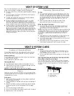
Page 17: ...s operating 2 Immediately turn off the downdraft vent at the speed control located on the right hand side of the downdraft vent 3 Turn off the power supply to the downdraft vent at the circuit breaker box or fuse box 4 Allow plenty of time for the downdraft vent to dry naturally Do not open the downdraft vent to remove the water VENT SYSTEM CARE Surface of Downdraft Vent To avoid damaging the fini...

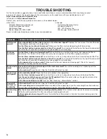
Page 18: ... it will go to activate the microswitch behind the filter Has the Start button been pressed for at least 3 seconds Push and hold the button on the top of the downdraft vent for at least 3 seconds to complete the cycle needed to start retracting Is the downdraft correctly secured Make sure that the vent hood is level and upright Check it is securely fastened to the floor and the counter top Vent pa...

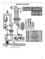
Page 19: ... Motor Resistance 120 VAC 60 Hz 420 W 3 7 A Blue White Blue Red Blue Gray Blue Black 21 6 Ohms 18 Ohms 14 3 Ohms 9 8 Ohms Blower Switch operation Contact Function 1 3 3 5 5 7 8 10 10 12 Off 1st Speed 2nd Speed 3rd Speed 4th Speed Num Filter microswitch 1 2 3 4 5 6 7 8 9 Filter microswitch Plenum Down Limit Switch Plenum Up Limit Switch Motor microswitch Plenum Drive motor Blower motor Blower Speed...

Page 20: ...u need further assistance you can write to Whirlpool Corporation with any questions or concerns at Whirlpool Brand Home Appliances Customer eXperience Center 553 Benson Road Benton Harbor MI 49022 2692 Please include a daytime phone number in your correspondence In Canada Call the Whirlpool Canada LP Customer eXperience Centre toll free at 1 800 6777 or visit our website at www whirlpool ca Our co...

Page 21: ...utions etc 5 Defects or damage caused by the use of non genuine Whirlpool parts or accessories 6 Conversion of products from natural gas or L P gas 7 Damage from accident misuse abuse fire floods acts of God or use with products not approved by Whirlpool 8 Repairs to parts or systems to correct product damage or defects caused by unauthorized service alteration or modification of the appliance 9 C...

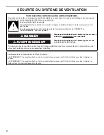
Page 22: ...areil ménager Assurez vous de toujours lire tous les messages de sécurité et de vous y conformer AVERTISSEMENT DANGER Voici le symbole d alerte de sécurité Ce symbole d alerte de sécurité vous signale les dangers potentiels de décès et de blessures graves à vous et à d autres Tous les messages de sécurité suivront le symbole d alerte de sécurité et le mot DANGER ou AVERTISSEMENT Ces mots signifien...

Page 23: ...e et évacuer adéquatement les gaz veiller à acheminer l air aspiré par un conduit jusqu à l extérieur ne pas décharger l air aspiré dans un espace vide du bâtiment comme une cavité murale un plafond un grenier un vide sanitaire ou un garage AVERTISSEMENT POUR RÉDUIRE LE RISQUE D INCENDIE UTILISER UNIQUEMENT DES CONDUITS MÉTALLIQUES AVERTISSEMENT POUR MINIMISER LE RISQUE D UN FEU DE GRAISSE SUR LA ...

Page 24: ...specter les dimensions indiquées pour les ouvertures à découper dans les placards Ces dimensions tiennent compte des valeurs minimales des dégagements de séparation Avant d effectuer des découpes consulter les instructions d installation fournies par le fabricant de la table de cuisson Vérifier qu à l emplacement d installation le système d extraction par le bas et la table de cuisson ne produiron...

Page 25: ...isinière Largeurs de la garniture supérieure 30 76 2 cm 36 91 4 cm 13 34 3 cm hauteur de l évacuation rétractable 27 68 6 cm pour une évacuation de 30 76 2 cm 33 83 8 cm pour une évacuation de 36 91 4 cm 16 42 0 cm 10 25 4 cm 2 5 4 cm 28 72 4 cm 0 95 cm 1 3 8 cm 13 33 4 cm 5 13 3 cm pour une évacuation de 30 76 2 cm 8 21 0 cm pour une évacuation de 36 91 4 cm 1 9 cm ...

Page 26: ...rge voir les illustrations suivantes Pour éviter une erreur avant de découper une ouverture il est recommandé de tracer le périmètre de la table de cuisson et des ouvertures à découper sur le plan de travail Pour les dimensions des ouvertures la position des ouvertures et le détail des installations voir les instructions d installation de la table de cuisson A B C E H D I G F A Système d extractio...

Page 27: ...ir à l extérieur Ne pas terminer le système d extraction dans un grenier ou dans un autre espace fermé Ne pas utiliser une bouche de décharge murale de 4 10 2 cm normalement utilisée pour un équipement de buanderie Ne pas connecter 2 coudes ensemble Ne pas utiliser un conduit de plastique ou en métal flexible La longueur du système d évacuation et le nombre de coudes doivent être réduits au minimu...

Page 28: ...on vers le bas B C A A Évacuation vers le bas B Évacuation à gauche C Évacuation à droite Configuration en îlot Circuit d évacuation installé sous une dalle de béton utilisation de conduit de PVC pour égout Ventilateur monté à l avant standard Ventilateur monté à l arrière A B C D E F G H I J K L M A B C D E F G H I J K L M A Bouche de décharge murale B Conduit métallique rond de dia 6 15 2 cm C 1...

Page 29: ...rd coudé à 90 de 6 15 2 cm vers 31 4 x 10 8 3 cm x 25 4 cm 5 0 pi 1 5 m Exemple de circuit d évacuation Dans l exemple suivant la longueur effective du circuit est inférieure au maximum de 35 pi 8 9 m 2 coudes à 90 10 pi 3 m 1 bouche de décharge murale 0 pi 0 m Section droite de 8 pi 2 4 m 8 pi 2 4 m Raccord de transition 4 5 pi 1 4 cm Longueur d un circuit de 6 15 2 cm ou 31 4 x 10 8 3 cm x 25 4 ...

Page 30: ... À deux personnes ou plus poser l arrière du système d extraction par le bas face au sol 2 Retirer les 4 vis du couvercle monté à l avant de la caisse du moteur et les mettre de côté 3 Faire glisser le couvercle vers le haut et le sortir des vis à épaulement pour encoches en trou de serrure Mettre le couvercle de côté 4 Retirer les 4 vis du bas de la caisse du moteur qui maintiennent le moteur à l...

Page 31: ...blage du ventilateur et mettre de côté la caisse du ventilateur 3 Ôter les 6 vis du rebord de montage du couvercle d épaisseur 1 4 6 4 mm B A C A A A Vis 7 B Vis à épaulement pour encoches en trou de serrure 2 C Caisse du ventilateur A A Caisse du moteur de ventilateur Vue arrière 4 Lever le couvercle d épaisseur 1 4 6 4 mm pour le sortir des vis à épaulement dans les encoches en trou de serrure e...

Page 32: ...e câblage au ventilateur 12 Monter la caisse du ventilateur sur la caisse du système d extraction et la fixer à l aide des 6 vis précédemment retirées A B A Platine de montage du câble B Œillet 13 Monter le couvercle de 43 4 12 0 cm fourni à l avant de la caisse du système d extraction Placer les encoches en trou de serrure par dessus les 2 vis à épaulement aligner les trous de montage et fixer le...

Page 33: ... 3 5 x 9 5 mm B Clapet anti retour de 3 x 10 8 3 cm x 25 4 cm A B A Vis de 3 5 x 9 5 mm B Raccord de transition rond de 6 15 2 cm avec clapet 2 Ôter les 4 vis du couvercle du boîtier de connexion 3 Déterminer par quel côté avant ou arrière le câble d alimentation domestique entre dans le boîtier de connexion Ôter l opercule approprié du panneau avant ou arrière et installer un connecteur de condui...

Page 34: ...u plan de travail C Orifices en trou de serrure D Guides A B C A Vis B Panneau anti éclaboussure C Plan de travail 7 Vérifier que le système d extraction par le bas est d aplomb vertical comme illustré Desserrer les vis des pieds de soutien inférieurs et régler les pieds de soutien en appui sur le plancher du placard 8 Fixer les pieds de soutien inférieurs de l appareil sur le plancher du placard ...

Page 35: ...le bas La section rétractable du système d extraction par le bas se déploie et le ventilateur peut être mis en marche à l aide du curseur de commande Retirer le film de protection et utiliser un nettoyant pour acier inoxydable pour enlever la graisse restante Positionner la garniture supérieure sur la section rétractable emboîter la garniture en place On peut trouver chez le revendeur local des en...

Page 36: ...ou augmenter le réglage de la flamme de la table de cuisson pour ce brûleur Utilisation du système d extraction par le bas Utilisation 1 Appuyer pendant quelques secondes sur le bouton au sommet de l appareil Ce léger délai permet d éviter un soulèvement accidentel de la partie rétractable du système d extraction par le bas lors du nettoyage de la table de cuisson La partie rétractable du système ...

Page 37: ...vers le bas 2 Laver le s filtre s métallique s selon le besoin au lave vaisselle ou avec une solution de détergent chaude 3 Réinstaller le filtre en s assurant que les poignées à ressort sont orientées vers l avant Insérer le filtre à graisse métallique dans la rainure supérieure 4 Tirer vers le bas sur la poignée à ressort 5 Pousser le filtre métallique vers le haut et relâcher la poignée pour l ...

Page 38: ... le système d extraction est entièrement déployé Les filtres sont ils bien installés Pousser le plus possible le filtre vers l intérieur pour activer le contact situé derrière le filtre Le curseur de commande est il toujours à la position fermé Pour sélectionner la vitesse du ventilateur utiliser le curseur de commande côté droit du conduit d évacuation par le bas Le ventilateur est il bien instal...

Page 39: ... W Bleu Blanc Bleu Rouge Bleu Gris Bleu Noir 21 6 Ohms 18 Ohms 14 3 Ohms 9 8 Ohms 3 7 A Remarque Le schéma de cáblage montre la fin de course en position basse Fonctionnement du commutateur du ventilateur Contact Fonction 1 3 3 5 5 7 8 10 10 12 1ére Vitesse 2e Vitesse Arrêt 3e Vitesse 4e Vitesse 1 2 3 4 5 6 7 8 9 Disposition des composants Description Num Microcontact du filtre Microcontact du fil...

Page 40: ...ire à Whirlpool en soumettant toute question ou tout problème à Whirlpool Brand Home Appliances Customer eXperience Center 553 Benson Road Benton Harbor MI 49022 2692 N oubliez pas d indiquer dans votre correspondance un numéro de téléphone où l on peut vous joindre dans la journée Au Canada Téléphoner sans frais au Centre pour l eXpérience de la clientèle Whirlpool Canada LP au 1 800 807 6777 ou ...

Page 41: ...té La présente garantie limitée est valable à compter de la date d achat initial par le consommateur Une preuve de la date d achat initial est exigée pour obtenir un dépannage dans le cadre de la présente garantie limitée 1 Usage commercial non résidentiel ou par plusieurs familles ou non respect des instructions de l utilisateur de l opérateur ou des instructions d installation 2 Visite d instruc...

Page 42: ...ou en cas de dépannage ou de réparation nécessaire sur ce gros appareil ménager autre que les responsabilités énoncées dans la présente garantie Si vous souhaitez une garantie plus étendue ou plus complète que la garantie limitée fournie avec ce gros appareil ménager adressez vous à Whirlpool ou à votre détaillant pour obtenir les modalités d achat d une garantie étendue LIMITATION DES RECOURS EXC...

Page 43: ...43 Notes ...

Page 44: ...W10342491F 2016 Whirlpool Used under license in Canada All rights reserved Utilisé sous licence au Canada Tous droits réservés 12 16 ...

Reviews: