20
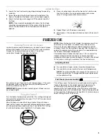
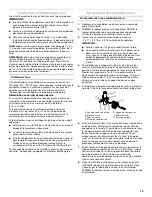
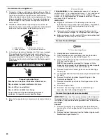
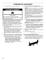
Raccordement au congélateur :
1.
Connecter le tube en plastique au robinet d’eau en utilisant
un écrou et une bague de compression tel qu’illustré. Serrer
l’écrou de compression. Ne pas serrer excessivement.
Utiliser la bride du tube à l'arrière du congélateur pour fixer le
tube au congélateur tel qu'illustré. Ceci aidera à empêcher
les dommages au tube lorsque le congélateur est poussé
contre le mur.
2.
OUVRIR le robinet d’arrêt. Inspecter pour rechercher les
fuites. Serrer tous les raccords (y compris les raccordements
de la valve d’entrée d’eau) ou les écrous qui coulent
.
3.
La machine à glaçons est équipée d’un filtre à eau incorporé.
Si la qualité de l’eau distribuée localement nécessite un
deuxième filtre à eau, il serait utile de l'installer dans le tube
de raccordement de
¹⁄₄
" (6,35 mm). On peut obtenir un tel
filtre à eau chez le marchand d’appareils électroménagers le
plus proche.
4.
Brancher le congélateur sur une priese à alevéoles reliée à la
terre.
Freezer Doors
TOOLS NEEDED:
⁵⁄₁₆
" hex-head socket wrench,
⁵⁄₈
" hex-head
socket wrench,
¹⁄₄
" hex-head socket wrench,
¹⁄₂
" hex-head socket
wrench,
³⁄₈
" hex-head socket wrench,
³⁄₁₆
" hex-head socket
wrench, #2 Phillips screwdriver, flat-blade screwdriver,
⁵⁄₁₆
" open-
end wrench, flat 2" putty knife.
IMPORTANT:
■
All graphics referenced in the following instructions are
included later in this section after “Final Steps.” The graphics
shown are for a right-hand swing door (hinges factory
installed on the right).
■
If you only want to remove and replace the door, see the
“Remove Door and Hinges” and “Replace Door and Hinges.”
■
Before you begin, turn the control OFF, and remove food and
adjustable door or utility bins from door.
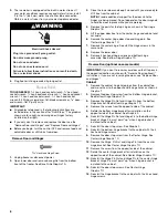
Remove Door and Hinges
⁵⁄₁₆
" Hex-Head Hinge Screw
1.
Unplug freezer or disconnect power.
2.
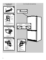
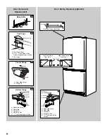
Open lower door and remove base grille from the bottom
front of the freezer. See Base Grille Graphic 1A.
3.
Close the lower door and keep it closed until you are ready to
lift it free from the cabinet.
NOTE:
Provide additional support for the door while the
hinges are being moved. Do not depend on the door magnets
to hold the door in place while you are working.
4.
Remove the parts for the top hinge as shown in Top Hinge
Graphic 1B.
5.
Lift the upper door free from the center hinge and cabinet and
set aside.
6.
Remove the center hinge door stop and hinge pin. See
Center Hinge Graphic 1C.
7.
Remove the center hinge. Reinstall the hinge screws in the
same holes.
8.
Remove the lower door.
9.
Remove 3 hex head hinge screws and bottom hinge
assembly. See Bottom Hinge Graphic 1D.
Reverse Door (optional on some models)
IMPORTANT:
If you want to reverse your door so that it opens in
the opposite direction, continue with “Reverse Door (optional)”
instructions. If you are not reversing the door, see “Replace Door
and Hinges.”
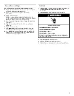
Cabinet
1.
Remove the cabinet hinge hole plugs from the cabinet top
and move them to the opposite side hinge holes as shown in
Graphic 1.
2.
Remove the door stop screw from the Bottom Hinge bracket.
See Bottom Hinge Graphic 1D.
A. Bride du tube
B. Tube en plastique
C. Écrou de compression
D. 4. Entrée d’eau de la valve
A
B
C
D
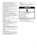
AVERTISSEMENT
Risque de choc électrique
Brancher sur une prise à 3 alvéoles reliée à la terre.
Ne pas enlever la broche de liaison à la terre.
Ne pas utiliser un adaptateur.
Ne pas utiliser un câble de rallonge.
Le non-respect de ces instructions peut causer
un décès, un incendie ou un choc électrique.

