background image

GB

29

Start-up and use

!

 The position of the corresponding gas burner or electric 

hotplate* is shown on every knob.

Gas  cooker  hobs  are  equipped  with  discrete  power 

adjustment that allows for accurately adjusting the flame to 5 

different power levels. Thanks to this system, gas hobs are 

also capable of guaranteeing the same cooking results for 

each recipe, as the optimal power level for the desired type 

of cooking can be identified in an easier, more accurate way.

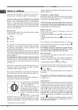
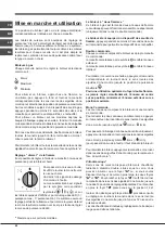
Gas burners

Each burner can be adjusted to one of the following settings 

using the corresponding control knob:

●  Off

 Maximum

 Minimum

To light one of the burners, hold a lit match or lighter near 

the burner and, at the same time, press down and turn the 

corresponding knob anti-clockwise to the maximum setting.

Since  the burner is  fitted with  a  safety device,  the  knob 

should be pressed for approximately 2-3 seconds to allow 

the automatic device keeping the flame alight to heat up.

When using models with an ignition button, light the desired 

burner pressing down the corresponding knob as far as possible 

and turning it anticlockwise towards the maximum setting.

!

 If a flame is accidentally extinguished, turn off the control 

knob and wait for at least 1 minute before trying to relight it.

To switch off the burner, turn the knob in a clockwise 

direction until it stops (when reaches the “●” position).

Discrete flame adjustment 

The selected burner can be adjusted - by means of the knob 

- to 5 different power levels. To shift between levels, simply 

turn the knob towards the desired power level.

A click signals the passage from one power level to the other.

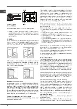
The selected power level is 

indicated by the corresponding 
symbol (symbols 

) and, 

on hobs equipped with a display, 

by the LEDs that turn on (5 = 

max. power; 1 = min. power). The 

system guarantees accurate flame 

adjustment and uniform cooking 

results by facilitating selection of the desired power level.

The “double-flame” burner

This gas burner consists of two concentric flame rings that can 

operate jointly or independently (in case of dual-control only).

As the burner is fitted with a safety device,

 the knob 

should be pressed down for approximately 2-3 seconds until 

the device keeping the flame automatically alight heats up.

Dual control:  

Each ring comprising the burner has its own control knob:

The knob marked with the symbol   controls the outer ring. 

The knob marked with the symbol   controls the inner ring.

To activate any one of the two rings, press the corresponding 

knob and turn it anti-clockwise to the maximum power 

setting 

.

In order to use the double-flame burner to its full 

potential, avoid simultaneously setting the inner ring to 

minimum power and the outer ring to maximum power.

Single control:

The rings comprising the burner are activated through a 

single control knob. 

To simultaneously turn on both rings, position the knob on 

the symbol  

 (max) -   (min) then press and turn the 

knob anti-clockwise.

To turn on the inner ring only, position the knob on the symbol 

 (max ) -   (min) then press and turn the knob clockwise.

(to switch modes, it is necessary to switch off the burner).

To switch off the burner, press and turn the knob clockwise 

until it stops (when it reaches the “●” position).

Ceramic Glass Module*

This cooktop is fitted with dual-ring radiant heating elements 

located beneath the glass. It is possible to turn on only the 

circular part of the elemement (identified by the letter 

“A”

) or 

the cooking surface can be enlarged by turning on both 

“A”


and 

“B”

. To turn only the circular 

“A”

 element, simply turn the 

knob in the clockwise direction to any one of the 12 available 

settings. To add the 

“B”

 section, turn the knob to setting 12 and 

then click it into the   setting. Then proceed by turning the knob 

in the counter-clockwise direction to  one of the 12 settings.

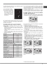
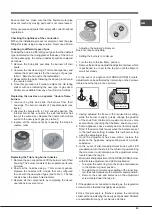
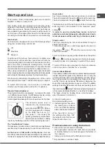
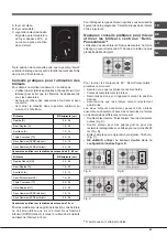
The figure shows the heating zones, which become red 

when the element is turned on.

A. Circular heating zone;

B. Extended heating zone;

C. Indicator light to show when 

the cooking zone is above  

60°C, even after the heating 

element has been turned off.

When the knob is on any of 

the settings other than “Off”, 

the Indicator Light for Ceramic 

Glass Module comes on.

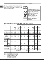
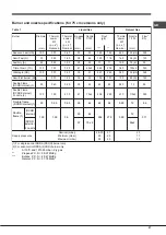
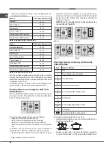
Practical advice on using the burners

To ensure the burners operate efficiently:

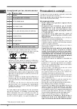
•  Use appropriate cookware for each burner (see table) 

so that the flames do not extend beyond the bottom of 

the cookware.

•  Always use cookware with a flat base and a cover.

A

C

B

*

 Only available on certain models. 

Summary of Contents for PK 630 RT GH/HA

Page 1: ...l uso 1 Avvertenze 3 Assistenza 7 Descrizione dell apparecchio 9 Installazione 12 Avvio e utilizzo 18 Precauzioni e consigli 20 Manutenzione e cura 21 Anomalie e rimedi 22 Contents Operating Instructions 1 Warnings 3 Assistance 7 Description of the appliance 9 Installation 23 Start up and use 29 Precautions and tips 31 Maintenance and care 31 Troubleshooting 32 Sommaire Mode d emploi 1 Avertisseme...

Page 2: ...a utilização 2 Advertências 5 Assistência 8 Descrição do aparelho 11 Instalação 58 Início e utilização 64 Precauções e conselhos 66 Manutenção e cuidados 67 Anomalias e soluções 68 Portuges Instruções para a utilização PLANO ...

Page 3: ...ica Nonutilizzaremaipulitoriavaporeoadalta pressione per la pulizia dell apparecchio Eliminare eventuali liquidi presenti sul coperchio prima di aprirlo Non chiudere il coperchio in vetro se presente con i bruciatori gas o la piastra elettrica ancora caldi L apparecchio non è destinato a essere messo in funzione per mezzo di un temporizzatore esterno oppure di un sistema di comando a distanza sepa...

Page 4: ...ns et par des personnes présentant des capacités physiques sensorielles ou mentales réduites ou n ayant pas l expérience ou les connaissances indispensables à condition qu ils soient sous bonne surveillance ou qu ils aient reçu les instructions nécessaires pour une utilisation de l appareil en toute sécurité et à condition qu ils se rendent compte des dangers encourus Les enfants ne doivent pas jo...

Page 5: ...ir la llama por ejemplo con una tapa o con una manta ignífuga ATENCIÓN Riesgo de incendio no deje objetos sobre las superficies de cocción ATENCIÓN Si la superficie de vitrocerámica está agrietada apague el aparato para evitar sacudidas eléctricas No utilice nunca limpiadores a vapor o de alta presión para la limpieza del aparato Elimine eventuales líquidos presentes sobre la tapa antes de abrirla...

Page 6: ...erâmica estiver rachada desligue o aparelho para evitar a possibilidade de choques eléctricos Nunca utilize equipamento de limpeza a vapor ou de alta pressão para limpar o aparelho Elimine os líquidos presentes na tampa antes de abri la Não feche a tampa de vidro se presente se os queimadores ou a chapa eléctrica ainda estiverem quentes O aparelho não é destinado a ser colocado em funcionamento po...

Page 7: ...minuto iva inclusa dal Lun al Ven dalle 18 30 alle 08 00 il Sab dalle 13 00 alle 08 00 e i giorni festivi per chi chiama dal telefono fisso Per chi chiama da radiomobile le tariffe sono legate al piano tariffario dell operatore telefonico utilizzato Le suddette tariffe potrebbero essere soggette a variazione da parte dell operatore telefonico per maggiori informazioni consultare il sito www indesi...

Page 8: ...8 Assistência Comunique o tipo de avaria o modelo da máquina Mod o número de série S N Estas últimas informações encontram se na placa de identificação situada no aparelho e ou na embalagem ...

Page 9: ...ne automatica del bruciatore prescelto DISPOSITIVO DI SICUREZZA in caso di spegnimento accidentale della fiamma interrompe l uscita del gas Presente solo in alcuni modelli Description of the appliance Overall view 1 Support Grid for COOKWARE 2 GAS BURNERS 3 CERAMIC GLASS MODULE 4 Control Knobs for GAS BURNERS 5 INDICATOR LIGHT FOR CERAMIC GLASS MODULE 6 Control Knobs for CERAMIC GLASS MODULE 7 Ign...

Page 10: ...sd extinctionaccidentelle de la flamme coupez immédiatement l arrivée du gaz N existe que sur certains modèles Descripción del aparato Vista en conjunto 1 Parrillas de apoyo para RECIPIENTES DE COCCIÓN 2 QUEMADORES A GAS 3 PLACA VITROCERÁMICA 4 Mandos de los QUEMADORES A GAS 5 PilotodefuncionamientodelaPLACAVITROCERÁMICA 6 Mandos de las PLACA VITROCERÁMICA 7 Bujía de encendido de los QUEMADORES A ...

Page 11: ...FUNCIONAMENTO CHAPA PARA COZER DE VIDRO CERÂMICA acende se se o selector estiveremqualquerposiçãodiferentedaqueladedesligado Os QUEIMADORES são de diferentes tamanhos e potências Escolha o mais adequado ao diâmetro do recipiente a ser utilizado Selectores de comando dos QUEIMADORES A GÁS e da VIDRO CERÂMICA para a regulação da chama ou da potência Vela para acender os QUEIMADORES A GÁS permite o a...

Page 12: ... di ventilazione con l esterno come sopra descritto e che non siano parti comuni dell immobile o ambienti con pericolo di incendio o camere da letto A Esempi di aperture di ventilazione per l aria comburente Maggiorazione della fessura fra porta e pavimento Locale adiacente Locale da ventilare I gas di petrolio liquefatti più pesanti dell aria ristagnano verso il basso Quindi i locali contenenti b...

Page 13: ...sicurezza Prima di effettuare l allacciamento accertarsi che la presa abbia la messa a terra e sia a norma di legge la presa sia in grado di sopportare il carico massimo di potenza della macchina indicato nella targhetta caratteristiche la tensione di alimentazione sia compresa nei valori nella targhetta caratteristiche la presa sia compatibile con la spina dell apparecchio In caso contrario sosti...

Page 14: ...iatore Tripla corona 1 togliere le griglie e sfilare i bruciatori dalle loro sedi Il bruciatore è composto da due parti separate vedi figure 2 svitare gli ugelli servendosi di una chiave a tubo da 7 mm Sostituire gli ugelli con quelli adattati al nuovo tipo di gas vedi tabella 1 I due ugelli hanno la stessa foratura 3 rimettere in posizione tutti i componenti seguendo le operazioni inverse rispett...

Page 15: ... 1 00 3 30 0 90 3 60 39 39 28 28 61 29 29 57 86 80 64 50 65x2 44 44 60x2 218 189 120 73 240 65 262 214 186 118 71 236 64 257 3 00 2 60 1 65 1 00 3 60 0 90 3 60 132 H3 122 H3 96 Z 79 6 103x2 74 74 94x2 286 248 157 95 343 86 343 Doppie fiamme 1 DCDR interno DCDR 2 ugelli per esterno 1 Solo per DCDR monocomando 2 Solo per DCDR doppio comando A 15 C e 1013 25 mbar gas secco Propano P C S 50 37 MJ Kg B...

Page 16: ...0 70 0 30 1 50 0 40 1 50 2 60 1 65 1 00 3 30 3 40 1 50 0 90 3 90 0 90 4 10 39 28 28 61 39 39 29 29 57 28 61 80 64 50 65x2 91 60 44 44 70x2 44 70x2 189 120 73 240 247 109 65 284 65 298 186 118 71 236 243 107 64 279 64 293 2 60 1 65 1 00 3 60 3 40 1 50 0 90 3 90 0 90 4 10 122 H3 96 Z 79 6 103x2 138 H3 88 X 72 72 96x2 74 110x2 248 157 95 343 324 143 86 371 86 390 Doppie fiamme 1 DCDR interno DCDR 2 u...

Page 17: ... non è al centro del bruciatore Nelle figure seguenti è indicato il giusto posizionamento OK ed alcuni esempi di posizionamento errato KO PK630RT PK630RTL TC DC S PK640 R S S A PK640R PK640RL PK640 1R PKS640R RR DC S A PK640 E X PK741RQO DC S A PK750 RR UR S S A PK750R PK750RL RR DC S S A PK750T PK750TL RR TC S S A PK750T E X PK750RT PK750RTL DC TC S A PK760RF RR DC SP A OK KO KO KO ...

Page 18: ...one della fiamma e permette di ottenere lo stesso risultato di cottura individuando più facilmente il livello di potenza desiderato Il bruciatore a doppie fiamme Questo bruciatore a gas è formato da due fuochi concentrici che possono funzionare insieme o in modo indipendente solo nel caso del doppio comando Poichè il bruciatore è dotato di dispositivo di sicurezza è necessario mantenere premuta la...

Page 19: ...recipienti cm 24 26 16 20 10 14 24 26 10 14 24 26 Pentole da usare sui piani 60 65 cm A C B Sui modelli dotati di griglietta di riduzione quest ultima dovrà essere utilizzata solo per il bruciatore Doppie Fiamme interno DCDR interno quando si utilizzano dei recipienti di diametro inferiore a 12 cm Per identificare il tipo di bruciatore fate riferimento ai disegni presenti nel paragrafo Caratterist...

Page 20: ...elativo al Posizionamento Le istruzioni sono valide solo per i paesi di destinazione i cui simboli figurano sul libretto e sulla targa matricola L apparecchio è stato concepito per un uso di tipo non professionale all interno dell abitazione L apparecchio non va installato all aperto nemmeno se lo spazio è riparato perché è molto pericoloso lasciarlo esposto a pioggia e temporali Non toccare la ma...

Page 21: ...oceramica Dapprima togliere dal piano di cottura tutti i resti di vivande e spruzzi di grasso con un raschietto per la pulizia per esempio non in dotazione Pulire il piano di cottura quando è tiepido utilizzare un prodotto di pulizia adatto come quello della linea Solutions disponibile presso tutti i Centri Assistenza Tecnica e carta da cucina strofinare con un panno umido ed asciugare Fogli di al...

Page 22: ...le vicinanze del piano La fiamma non rimane accesa nelle versioni con sicurezza Avete controllato se Non avete premuto a fondo la manopola Non avete mantenuto premuta a fondo la manopola per un tempo sufficiente ad attivare il dispositivo di sicurezza Sono ostruiti i fori di fuoriuscita del gas in corrispondenza del dispositivo di sicurezza Il bruciatore in posizione di minimo non rimane acceso Av...

Page 23: ...However these rooms must not be communal rooms bedrooms or rooms that may present a fire hazard Liquid petroleum gas sinks to the floor as it is heavier than air Therefore rooms containing LPG cylinders must also be equipped with vents to allow gas to escape in the event of a leak As a result LPG cylinders whether partially or completely full must not be installed or stored A Examples of ventilati...

Page 24: ...hat The appliance is earthed and the plug is compliant with the law The socket can withstand the maximum power of the appliance which is indicated on the data plate The voltage is in the range between the values indicated on the data plate The socket is compatible with the plug of the appliance If the socket is incompatible with the plug ask an authorised technician to replace it Do not use extens...

Page 25: ...able 1 The two nozzles have the same hole diameter 3 Replace all the components by completing the above operations in reverse order Adjusting the burners primary air Does not require adjusting Setting the burners to minimum 1 Turn the tap to the low flame position 2 Remove the knob and adjust the adjustment screw which is positioned in or next to the tap pin until the flame is small but steady In ...

Page 26: ...p c s p c s p c s mm Reduced Nominal mm mm Nominal mm Supply pressures Nominal mbar Minimum mbar Maximum mbar 28 30 20 35 37 25 45 20 17 25 Fast R Reduced Fast RR Semi Fast S Auxiliary A Triple Crown TC 100 100 75 55 130 0 70 0 70 0 40 0 40 1 50 3 00 2 60 1 65 1 00 3 30 39 39 28 28 61 86 80 64 50 65x2 218 189 120 73 240 214 186 118 71 236 3 00 2 60 1 65 1 00 3 60 132 H3 122 H3 96 Z 79 6 103x2 286 ...

Page 27: ... 70 0 70 0 40 1 50 2 60 1 65 1 00 3 30 3 40 1 50 0 90 4 10 39 28 28 61 39 39 28 61 80 64 50 65x2 91 60 44 70x2 189 120 73 240 247 109 65 298 186 118 71 236 243 107 64 293 2 60 1 65 1 00 3 60 3 40 1 50 0 90 4 10 122 H3 96 Z 79 6 103x2 138 H3 88 X 74 110x2 248 157 95 343 324 143 86 390 Double flame DCDR internal 1 30 0 30 0 90 29 44 65 64 0 90 72 86 Double flame 1 DCDR internal DCDR external 2 nozzl...

Page 28: ... TC S S A PK750T E X PK750RT PK750RTL DC TC S A PK760RF RR DC SP A For model PK 640 1 only The grids may be positioned incorrectly If this happens the spokes will appear particularly misaligned and the intersection point will no longer be at the centre of the burner The figures below illustrate correct positioning OK and some examples of incorrect positioning KO OK KO KO KO ...

Page 29: ...he knob should be pressed down for approximately 2 3 seconds until the device keeping the flame automatically alight heats up Dual control Each ring comprising the burner has its own control knob The knob marked with the symbol controls the outer ring The knob marked with the symbol controls the inner ring To activate any one of the two rings press the corresponding knob and turn it anti clockwise...

Page 30: ...used To turn the two burners 90 proceed as follows Make sure that the burners are cool Lift the burner completely out of its housing Replace it in its housing in the position desired Make sure that the burners are positioned correctly before use In addition the two burners can be used in tandem or speartely with cookware of different shapes and sizes Double burner for a fish kettle or oval cookwar...

Page 31: ...es should you attempt to repair the appliance yourself Repairs carried out by inexperienced persons may cause injury or further malfunctioning of the appliance Contact a Service Centre see Assistance Always make sure that pan handles are turned towards the centre of the hob in order to avoid accidental burns Do not close the glass cover if present when the gas burners or electric hotplates are sti...

Page 32: ... hot grids on top of the glass cover if applicable otherwise the rubber plugs on the glass may be damaged Clening tips for the hotplates with logo To remove all types of stains just wipe with a smooth cloth wet with hot water For stronger stains we recommend the use of common detergent for dishes with a cloth dampened with hot water to ensure a perfect cleaning result Is not recommended to use rou...

Page 33: ...uivantes Lapiècedoitprévoirunsystèmed évacuationversl extérieur des fumées de combustion réalisé au moyen d une hotte ou par ventilateur électrique qui entre automatiquement en fonction dès que l on allume l appareil La pièce doit prévoir un système qui consent un apport d air nécessaire à une régulière combustion Le flux d air nécessaire à la combustion ne doit pas être inférieur à 2 m3 h par kW ...

Page 34: ...au dessus d un four à encastrer la connexion électrique de la table et celle du four doivent être effectuées séparément pour des questions de sécurité électrique mais aussi pour simplifier au besoin l extraction du four Branchement du câble d alimentation au réseau électrique Montez sur le câble une prise normalisée adaptée à la charge indiquée sur l étiquette des caractéristiques Encasderaccordem...

Page 35: ... le raccord vous devez obligatoirement remplacer le joint d étanchéité fourni avec l appareil Le raccord d entrée du gaz à l appareil est fileté 1 2 gaz mâle cylindrique Raccordement par tuyau flexible en acier inox à paroi continue avec raccords filetés Le raccord d entrée du gaz à l appareil est fileté 1 2 gaz mâle cylindrique L G R La mise en œuvre de ces tuyaux doit être effectuée de façon à c...

Page 36: ...et d affichage à led positionner la manette sur le minimum retirer ensuite la manette et agir sur la vis de réglage située à côté de la tige du robinet 7 Réglage des minima du brûleur DCDR à réglage discret et à affichage à led pour le réglage de l anneau extérieur tourner la manette dans le sens inverse des aiguilles d une montre jusqu à la position minimum pour le réglage du minimum de l anneau ...

Page 37: ...ue kW p c s Nominale Injecteur 1 100 mm Débit g h 3 00 2 60 1 65 1 00 3 30 332 288 183 111 365 G25 Puissance thermique kW p c s Nominale Débit l h Caractéristiques des brûleurs et des injecteurs uniquement pour modèles 60 et 65 cm Pour la Hollande Pressions d alimentation Nominale mbar Minimum mbar Maximum mbar 25 20 30 Rapide R Rapide Réduit RR Semi Rapide S Auxiliaire A Triple Coronne TC 100 100...

Page 38: ...le mbar Minimum mbar Maximum mbar 20 17 25 Rapide R Rapide Réduit RR Semi Rapide S Auxiliaire A Triple Coronne TC 100 100 75 55 130 0 70 0 70 0 40 0 40 1 50 3 00 2 60 1 65 1 00 3 60 132 H3 122 H3 96 Z 79 6 103x2 Brûleur Diamêtre mm Puissance thermique kW p c s Réduit Nominale Injecteur 1 100 mm 286 248 157 95 343 G20 Débit l h Gaz natural Cat I2E 130 3 60 1 50 74 94x 2 343 74 Deux flammes DCDR Int...

Page 39: ...sance thermique kW p c s Réduit Puissance thermique kW p c s Nominale By pass 1 100 mm Injecteur 1 100 mm Débit g h Butane Propane G20 Puissance thermique kW p c s Nominale Injecteur 1 100 mm Débit g h 2 60 1 65 1 00 3 30 3 40 1 50 0 90 4 10 288 183 111 365 376 166 100 454 G25 Puissance thermique kW p c s Nominale Débit l h Caractéristiques des brûleurs et des injecteurs uniquement pour modèles 75...

Page 40: ...imum mbar 20 17 25 Rapide Réduit RR Semi Rapide S Auxiliaire A Triple Coronne TC Ultra Rapide UR Semi Poissonière SP Doppie Fiamme DCDR Intérieur 2 Doppie Fiamme DCDR Extérieur 2 injecteurs 2 100 75 55 130 100 30 130 0 70 0 40 0 40 1 50 0 70 0 70 0 40 1 50 2 60 1 65 1 00 3 30 3 40 1 50 0 90 4 10 122 H3 96 z 79 6 103x2 138 H3 88 X 74 110x2 Brûleur Diamêtre mm Puissance thermique kW p c s Réduit Nom...

Page 41: ...RR TC S S A PK750T E X PK750RT PK750RTL DC TC S A PK760RF RR DC SP A Uniquement pour le modèle PK 640 1 Les grilles peuvent être mal positionnées Dans ce cas le décalage des porte casseroles est très évident et ceux ci ne seront plus centrés sur le brûleur Le bon positionnement OK et quelques exemples de mauvais positionnement KO sont illustrés sur les figures suivantes OK KO KO KO ...

Page 42: ... désiré Le brûleur à deux flammes Ce brûleur à gaz est formé de deux anneaux de flamme concentriques pouvant fonctionner ensemble ou séparément uniquement dans le cas de double commande Le brûleur étant équipé d un dispositif de sécurité de flamme appuyer pendant au moins 2 3 secondes de suite sur la manette pour permettre au dispositif de se réchauffer Double commande Chaque couronne composant le...

Page 43: ...cuisson de 60 65 cm Sur les modèles munis de grille de réduction cette dernière ne doit être utilisée que sur le brûleur Deux flammes intérieur DCDR intérieur lorsque l on utilise des récipients de diamètre inférieur à 12 cm A C B Pour distinguer le type de brûleur reportez vous aux dessins figurant dans le paragraphe Caractéristiques des brûleurs et des injecteurs Quelques conseils pratiques pour...

Page 44: ...urnies ne sont applicables qu aux pays dont les symboles sont reportés dans la notice et sur la plaquette d immatriculation Cet appareil a été conçu pour un usage familial de type non professionnel Cet appareil ne doit pas être installé en extérieur même dans un endroit abrité il est en effet très dangereux de le laisser exposé à la pluie et aux orages Ne touchez pas à l appareil si vous êtes pied...

Page 45: ...tifs d allumage électronique instantané et vérifiez que les orifices de sortie du gaz ne sont pas bouchés Avant de commencer à cuisiner nettoyez la surface à l aide d un chiffon humide pour éliminer toute trace de poussière ou de résidus d aliments cuits auparavant Nettoyez régulièrement la surface de la table en utilisant une solution d eau tiède et de détergent non abrasif Il faudra utiliser de ...

Page 46: ...en amont de l appareil sont bien ouverts Le brûleur ne s allume pas ou la flamme n est pas uniforme Avez vous contrôlé si les orifices de sortie du gaz ne sont pas par hasard bouchés les pièces amovibles composant le brûleur sont bien montées correctement il y a des courants d air dans les environs du plan de cuisson La flamme s éteint dans les versions équipées de sécurité de flamme Avez vous con...

Page 47: ...scon peligro de incendio o dormitorios A Ejemplos de aperture de ventilación para aire comburente Aumento de la ranura entre puerta y suelo Habitación adyacente Habitación por ventilar Los gases de petróleo licuados más pesados que el aire se depositan en las partes más bajas Por lo tanto los ambientes que contienen botellas de GPL deben tener aberturas hacia el exterior para permitir la evacuació...

Page 48: ...ingún punto una temperatura que supere en 50 C la temperatura ambiente El instalador es responsable de la correcta conexión eléctrica y del cumplimiento de las normas de seguridad Antes de efectuar la conexión verifique que la toma tenga conexión a tierra y que sea conforme con la ley la toma sea capaz de soportar la carga máxima de potencia de la máquina indicada en la placa de características la...

Page 49: ...s posiciones efectuando las operaciones inversas respecto a la secuencia arriba indicada Cambio de los picos en el quemador Triple corona 1 quitarlasrejillasyextraerlosquemadores Elquemadorestá compuesto por dos partes separadas ver las figuras 2 desenrosque los inyectores utilizando una llave tubular de 7 mm Sustituir los picos con los adecuados al nuevo tipo de gas ver la tabla 1 Los dos inyecto...

Page 50: ...ido Gas natural Quemador Diametro Potencia Potencia By pass Pico Capacid Potencia Pico Capacid térmica térmica 1 100 1 100 g h térmica 1 100 l h kW kW kW p c s p c s p c s mm Reducida Nominal mm mm Nominal mm Presiones de suministro Nominal mbar Minimo mbar Màximo mbar 28 30 20 35 37 25 45 20 17 25 Ràpido R Ràpido Reduc RR Semi Ràpido S Auxiliar A Corona Triple TC 100 100 75 55 130 0 70 0 70 0 40 ...

Page 51: ...0 40 0 40 1 50 0 70 0 70 0 40 1 50 2 60 1 65 1 00 3 30 3 40 1 50 0 90 4 10 39 28 28 61 39 39 28 61 80 64 50 65x2 91 60 44 70x2 189 120 73 240 247 109 65 298 186 118 71 236 243 107 64 293 2 60 1 65 1 00 3 60 3 40 1 50 0 90 4 10 122 H3 96 Z 79 6 103x2 138 H3 88 X 74 110x2 248 157 95 343 324 143 86 390 Doble llama 1 DCDR Interno 130 1 50 3 90 29 44 284 279 3 90 72 371 DCDR Externo 2 pico 57 70x2 96x2...

Page 52: ...50T E X PK750RT PK750RTL DC TC S A PK760RF RR DC SP A Sólo para el modelo PK 640 1 Es posible que las rejillas se coloquen de modo incorrecto En este caso la no alineación de las hornallas es evidente y el cruce de las mismas no está en el centro del quemador En las siguientes figuras se indica el posicionamiento adecuado OK y algunos ejemplos de posicionamiento incorrecto KO OK KO KO KO ...

Page 53: ...una perfecta regulación de la llama y permite obtener el mismo resultado de cocción individualizando más fácilmente el nivel de potencia deseado El quemador de dos llamas Este quemador a gas está formado por dos fuegos concéntricos que pueden funcionar juntos o de manera independiente sólo en el caso del doble mando Debido a que el quemador está dotado de un dispositivo de seguridad es necesario m...

Page 54: ...entes cm 24 26 16 20 10 14 24 26 10 14 24 26 Ollas que deben utilizarse en placas de 60 65 cm En los modelos dotados de rejilla de reducción esta última deberá ser usada únicamente para el quemador Doble llama interno DCDR Interno cuando se usan recipientes de diámetro inferior a 12 cm A C B Para identificar el tipo de quemador ver los diseños presentes en el párrafo Características de los quemado...

Page 55: ...te a la Colocación Las instrucciones son válidas sólo para los países de destino cuyos símbolos figuran en el manual y en la placa de características El aparato ha sido fabricado para un uso de tipo no profesional en el interior de una vivienda El aparato no se debe instalar al aire libre tampoco si el espacio está protegido porque es muy peligroso dejarlo expuesto a la lluvia y a las tormentas No...

Page 56: ...a y detergente suave Periódicamente es necesario efectuar una limpieza esmerada con producto especial para l i m p i e z a d e p l a c a s d e vitrocerámica En este caso se quitará cualquier residuo incrustación o salpicadura utilizando el raspador especial por ej que no viene en dotación Limpiar la placa mientras está tibia usar una preparación adecuada como el de la línea Solutions disponible en...

Page 57: ...lida de gas del quemador están obstruidos Se han colocado correctamente todas las partes móviles que componen el quemador Hay corriente de aire en las cercanías de la encimera La llama no permanece encendida en los modelos con seguridad Controle si No ha presionado a fondo el mando No ha mantenido presionado a fondo el mando por un tiempo suficiente como para activar el dispositivo de seguridad Es...

Page 58: ... com perigo de incêndio nem quartos de dormir que possuam um conduto de ventilação comunicadora com a parte externa Os gases de liquefeitos de petróleo mais pesados do que o ar estagnam se embaixo Portanto as salas que A Exemplos de abertura de ventilação para ar comburente Aumento da fenda entre porta e soalho Local adjacente Local a ser ventilado contiverem cilindros de GLP devem possuir abertur...

Page 59: ... C a temperatura do ambiente O técnico instalador é responsável pela realização certa da ligação eléctrica e da obediência das regras de segurança Antes de efectuar a ligação certifique se que a tomada tenha uma ligação à terra e seja em conformidade com a legislação a tomada tenha a capacidade de suportar a carga máxima de potência da máquina indicada na placa de identificação a tensão de aliment...

Page 60: ... ver tabela 1 3 colocar no lugar todos os componente seguindo as operações contrárias às da sequência citada acima Substituição dos bicos do queimador de tripla coroa 1 retire as grelhas e extraia os queimadores das suas sedes O queimador é composto por duas partes separadas ver figuras 2 desenrosque os bicos utilizando uma chave de tubo de 7 mm Troque os bicos por outros adequados ao novo tipo de...

Page 61: ...S CARACTERÍSTICAS ver quadro das características Este aparelho é em conformidade com as seguintes Directivas da Comunidade Europeia 2006 95 CEE de 12 12 06 Baixa Tensão e posteriores modificações 2004 108 CEE de 15 12 04 Compatibilidade Electromagnética e posteriores modificações 93 68 CEE de 22 07 93 e posteriores modificações 2009 142 CEE de 30 11 09 Gás e posteriores modificações 2012 19 CEE e ...

Page 62: ...9 44 262 257 3 60 74 343 DCDR Externo 2 bico 57 60x2 94x2 Características dos queimadores e bicos somente para os modelos 60 e 65 cm 1 Apenas para DCDR monocomando 2 Apenas para DCDR de duplo comando A 15 C e 1013 25 mbars gás seco Propano P C S 50 37 MJ Kg Butano P C S 49 47 MJ Kg Natural P C S 37 78 MJ m 30 0 30 0 90 29 44 65 64 0 90 74 86 Chama Duplas DCDR Interno 1 Chama Duplas DCDR Interno 2 ...

Page 63: ...0 40 1 50 0 70 0 70 0 40 1 50 2 60 1 65 1 00 3 30 3 40 1 50 0 90 4 10 39 28 28 61 39 39 28 61 80 64 50 65x2 91 60 44 70x2 189 120 73 240 247 109 65 298 186 118 71 236 243 107 64 293 2 60 1 65 1 00 3 60 3 40 1 50 0 90 4 10 122 H3 96 Z 79 6 103x2 138 H3 88 X 74 110x2 248 157 95 343 324 143 86 390 Chamas Duplas 1 DCDR Interno 130 1 50 3 90 30 0 30 0 90 29 44 29 44 284 279 3 90 65 64 0 90 72 72 371 86...

Page 64: ...ltado de cozedura identificando mais facilmente o nível de potência desejado O queimador com duplas chamas Este queimador a gás é constituído por dois fogos concêntricos que podem funcionar juntos ou de maneira independente apenas em caso de duplo comando Como o queimador está equipado com um dispositivo de segurança é necessário manter o botão pressionado cerca de 2 3 segundos até que aqueça o di...

Page 65: ...4 24 26 Panelas para usar nos planos de 60 65 cm A C B Nos modelos equipados com grelha de redução a mesma deverá ser utilizada sòmente para o queimador Chamas Duplas Interno DCDR Interno quando se utilizam recipientes de diâmetro inferior a 12 cm Para identificar o tipo de queimador consultar os desenhos apresentados no parágrafo Características dos queimadores e dos bicos Conselhos práticos para...

Page 66: ...ente Assegurar se que sejam respeitados os requisitos do parágrafo Posicionamento no momento da instalação As instruções são válidas somente para os países de destino para os quais os símbolos constam no livrete e na placa de identificação do aparelho Este aparelho foi concebido para utilização de tipo não profissional no âmbito de moradas Este aparelho não deve ser instalado ao ar livre mesmo num...

Page 67: ...spositivos de acendimento electrónico instantâneo e é também necessário verificar que os orifícios de saída do gás não estejam entupidos antes de começar a cozer a superfície da chapa deve ser limpa utilizando um pano húmido para remover a poeira ou resíduos de alimentos anteriormente cozidos A superfície da chapa deverá ser limpa regularmente com água morna e um detergente não abrasivo Periodicam...

Page 68: ...redes de alimentação de gás e electricidade especialmente se as torneiras do gás antes do plano estão abertas O queimador não se acende ou a chama não é uniforme Foi controlado se Estão entupidos os furos de saída do gás do queimador Estão instalados correctamente todos os componentes móveis que compõem o queimador Há correntes de ar nas proximidades do plano A chama não permanece acesa nas versõe...

Reviews: