6
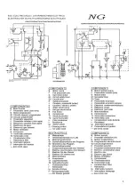
OPERATING PRINCIPLE FOLLOWING THE ELECTRIC DIAGRAM (TIMER ON
DEFROST - MICROSWITCHES DEPRESSED)
.
- The ITV model NG has two switches:
1
st
In the frontal side of the machine (with led). This turns the machine on or off when we
press it.
2
nd
The second switch is located in the electrical panel. This one stops the condensing unit,
but keeps the hydraulic part in operation and allows to do the cleaning of the machine
(except in NDP20 model).
- Current reaches the machine via the line connecting the blue (1) and brown (2)
terminals. The brown wire connects the compressor and timer motor. The blue wire
connects bin thermostat T1 which closes the circuit with 2. A different blue wire goes to 2
on terminal G1 which at this moment is connecting 1 and 4.
- A red wire connects bin thermostat T1 and micros G1 and G2 which close the
circuit with 4 and provide current via G1 to the timer G
.
- At this point the following are connected:
v
COMPRESSOR (S)
v
WATER INLET VALVE (P)
v
HOT GAS VALVE (Q)
v
TIMER MOTOR (G)
- Since the motor of the timer (G) is working, during 1
÷
3 minutes the roler of micro of the
second water inlet coil (cleaning valve drive) is depressed until the pins release the micro,
closing this valve..
- After
2 to 4 minutes micros G1 and G2 will open and close circuits 1-2.
-
Via terminal 2 on micro G2, current reaches the pump. Circuit 4 on micro G2 which
provides current to the hot gas valve (Q) and water inlet valve (P) will be interrupted. Since
the thermostat is between 1 and 3 the timer will receive no current. The compressor
continues switched on.
Summary of Contents for ICE CUBES MAKERS Series
Page 1: ...ICE CUBES MAKERS Range SPRAY Technology ...
Page 8: ...8 ...
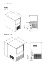
Page 9: ...9 SPECIFICATIONS Models NDP 20 NG DP 30 150 ...

