background image

19

*These instructions are brief and intended as guidance for a quali

fi

 ed person. If you lack the necessary

skills to perform these procedures call 1-877-817-6750 for assistance.

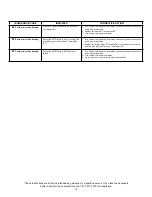
Diagnostic Code Chart  

Electronic Thermostat (ET)

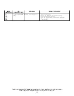
(ESM)

ERROR CODE

(ET)

DIAGNOSTIC LED

INDICATES

CORRECTIVE ACTION*

LIGHT ON
(Green Flash)

Normal operation.

None

NO LIGHT

No electrical power to control board
or diagnostic LED light burned out.

1.  Check for blown fuses or tripped breaker.
2.  If diagnostic LED light is burned out, replace Electronic Thermostat 
     (ET).

E01

1 FLASH
(Red)

Dry-fire, electrical power on with the 
tank not completely full of water.

1.  Turn off electrical power at breaker, add water. 
2.  Turn on electrical power at breaker.
3.  See “Water Heater Start-Up” on page 10.

E02

2 FLASHES
(Red)

Water temperature exceeded high 
limit.

1.  Turn off electrical power at the breaker.
2.  Press the reset button (see Figure 10A).
3.  Turn on electrical power at breaker.
4.  If error returns call a service technician for assistance.

E03

3 FLASHES
(Red)

Upper thermistor sensor failure.
(Note: Upper thermistor sensor is
part of the ET)

1.  Turn off electrical power at the breaker.
2.  Replace Electronic Thermostat (ET).
3.  Turn on electrical power at breaker.

E04

4 FLASHES
(Red)

Upper element circuit failure.
(Note: Lower element is still operable)

1.  Turn off electrical power at the breaker.
2.  Check element circuits for resistance of 5-25 ohms (replace if required).
3.  Check wires at elements and Electronic Thermostat (ET) for damage. 
     If this 4 flashes condition continues, replace Electronic Thermostat (ET).
4.  Turn on electrical power at breaker. 

E05

5 FLASHES
(Red)

Lower element circuit failure.
(Note: Upper element is still operable)

1.  Turn off electrical power at the breaker.
2.  Check element circuits for resistance of 5-25 ohms (replace if required).
3.  Check wires at elements and Electronic Thermostat (ET) for damage.
     If this 5 flashes condition continues, replace Electronic Thermostat (ET).
4.  Turn on electrical power at breaker.

E06

6 FLASHES
(Red)

Electronic Thermostat (ET) failure
(Internal processor).

1.  Turn off electrical power at the breaker. Now turn on electrical power to 
     see if error clears. If error has not cleared, replace Electronic Thermo-
     stat (ET).
2.  Turn on electrical power at breaker.

E07

7 FLASHES
(Red)

Lower thermistor sensor failure.

1.  Turn off electrical power at the breaker.
2.  Check electrical connections at Electronic Thermostat (ET).
3.  Replace Lower Thermistor Sensor.
4.  Turn on electrical power at breaker.

E08

8 FLASHES
(Red)

Energy Smart

®

 Interface 

Module(ESM) failure.

1.  Turn off electrical power.                    
2.  Check wires at the interface module for damage.
3.  If this 8 flashes condition continues, replace module (ESM).
4.  See “Overriding The Interface Module (ESM)” by unplugging from the 
     Electronic Thermostat (ET) on page 12. NOTE: Electronic Thermostat 
     (ET) will continue to be operate, hot water will still be available.
5.  Turn on electrical power at breaker.

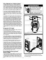
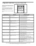
Setpoint

K

nob

Diagnosti

c

LED


Light

P

l

asti

Guard

Electrical Shock Hazard

Do not remove the plactic 

guard from over wiring.

Do not touch electrical wiring.


Failure to do so can result in 

death or electrical shock.

IMPORTANT: Before attempting to adjust the ther-
mostat, read the “Water Temperature Regulation” 
section page 10. 

The Electronic Thermostat (ET) is designed so 
that it may control the water heater without the 
Energy Smart

®

 Module (ESM) being operated, 

see page 12.

If the instructions are not clear, contact a quali

fi

 ed 

person.

Summary of Contents for Energy Smart 188410

Page 1: ...allation 2 7 Digit Product Number 5 Place of Purchase 3 Serial Number Table Of Contents PAGE Water Heater Safety 2 Installing Your Electric Water Heater 3 9 Unpacking Instructions 3 Location Requirements 4 Water System Piping 5 Electrical Requirements 7 Installation Checklist 9 Operating Your Water Heater 10 12 Water Heater Start Up 10 Water Temperature Regulation 10 Energy Smart Module Operationa...

Page 2: ...served by this heater that has not been used for a long period of time 2 weeks or more Hydrogen is extremely flammable To reduce the risk of injury under these conditions it is recommended that the hot water faucet be opened for several minutes at the kitchen sink before using any electrical appliance connected to the hot water system When hydrogen is present there will probably be an unusal sound...

Page 3: ...y be fore attempting the installation or operation of this water heater This manual should be kept for future reference The manufacturer of this water heater will not be liable for any damages caused by failure to comply with the instal lation and operating instructions outlined in this manual If you lack the necessary skills required to properly install this water heater or you have difficulty fo...

Page 4: ... including those from improper installation may cause early failure of the water tank due to corrosion if not repaired If the homeowner is uncomfortable with making the repair a qualified person should be contacted A suitable metal drain pan should be installed under the water heater as shown below This metal drain pan is to protect the property from damage which may occur from normal condensate f...

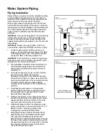
Page 5: ...he cold water line as specified under Closed System Thermal Expansion 5 Install a shut off valve in the cold water inlet line It should be located close to the water heater and be easily accessible Know the location of this valve and how to shut off the water to the heater 6 Install a discharge line from the temperature and pressure relief valve in the opening marked T P RELIEF VALVE Install as sp...

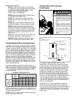
Page 6: ...ng service agency or your retail supplier regarding the installation of a ther mal expansion tank Temperature and Pressure Relief Valve Figure 5 Temperature and Pressure Relief Valve Installation Optional location some models only Temperature and Pressure Relief Valve Discharge Line 3 4 inch min Do not cap or plug 6 inch maximum Drain Pan Drain GRID ENABLED VACATION STANDARD ENERGY SMART F C F For...

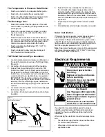
Page 7: ...f pipe insulation 6 Spread the slit open and slip the insulation over the cold water inlet pipe Apply gentle pressure along the length of the insulation to ensure it is fully seated around the pipe Also ensure that the base of insulation is flush with the water heater Once seated secure the insulation with duct tape electrical tape or equivalent 7 Repeat steps 5 through 6 for the hot water outlet ...

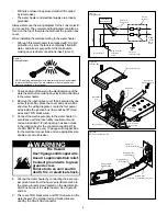
Page 8: ...trical Service ground Ring Terminal at Ground Screw Red Black Approved Connectors Water Heater Smart Grid Wire Harness Black R e d Green Fire Hazard Use 10 gauge solid copper wire Use a UL approved strain relief Connect ground wire to green ground screw Failure to do so can result in death fire or electrical shock WARNING 1 Check and turn off power to the electrical wiring of the water heater befo...

Page 9: ... buildup precautions installed See Closed System Thermal Expansion section Mixing valve when applicable installed per manufac turer s instructions see Figure 4 Electrical Connections Wiring and connections comply with all applicable codes Water heater and electrical supply are properly grounded Proper overload fuse or circuit breaker protection installed 6 Connect the black power wire from the hom...

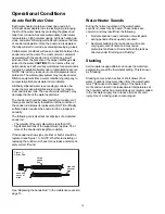
Page 10: ... event that the water temperature exceeds 180 F 82 2 C A temperature limit switch or ECO Energy Cut Off is used to shut off the power to the system if the wa ter temperature exceeds 180 F or 82 2 C The ECO can be reset by firmly pushing in the red reset button located on the electronic thermostat see Figure 10A on page 12 If the ECO continues to shut off the water heater contact a qualified person...

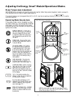
Page 11: ...en ergy consumption and prevents the water heater from freezing during cold weather GRID ENABLED Pressing this button will enable or disable a re quest for grid control see page 13 CONTROL PANEL LOCK Holding this button for more than 3 seconds switches the lock mode on or off When the User Module is locked a symbol and Lock text will be visible on the display 0 F 0 C This button switches the displ...

Page 12: ...nt is powered Red LED will flash error codes If a fault is detected by the electronic thermostat the LED light indicator will use the red LED to indicate the fault detected The flash code sequence is to consist of 1 2 second flashes of the red LED each separated by a 1 2 second off period The number of flashes indicates the fault code number See diagnostic code chart section in this manual After t...

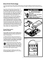
Page 13: ...ultimately save money Smart Grid Control Where Available Where available Grid Communication Adaptors may be supplied by the local power company or purchased from leading retailers Please contact your local power com pany for more information To activate SmartGrid Control remove the cover over the grid connection pins and plug in the grid communica tion adaptor See Figure 10C NOTE use only Whirlpoo...

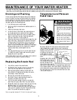
Page 14: ...on of the anode rod dictates its replacement NOTE artificially softened water requires the anode rod to be inspected annually The following are typical but not all signs of a depleted anode rod The majority of the rods diameter is less than 3 8 Significant sections of the support wire approx 1 3 or more of the anode rod s length are visible If the anode rod show signs of either or both it should b...

Page 15: ... allow water to run until the air is purged and the water flows uninterrupted from the faucet 7 Turn the electrical power on to turn the water heater on NOTE the water heater will conduct a system diagnostic prior to operation If the water heater is going to be shut down for an extend ed period the drain valve should be left open Replacing the Anode Rod 1 Turn off the power to the water heater 2 S...

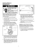
Page 16: ...cate the new gasket with a few drops of dishwashing soap position the new gasket on the element and insert it into the water heater tank See Figure 14 Tighten the element by turning it clockwise until secure Ground Wire green Figure 13 Element Wiring Connection Screws Wires Element Lower Thermistor Sensor 7 Close the drain valve Open the nearest hot water faucet and allow the tank to fill complete...

Page 17: ...Check wires at elements and Electronic Thermostat ET for damage If this 5 flashes condition continues replace Electronic Thermostat ET 4 Turn on electrical power at breaker E06 with an alert Icon flashing Electronic Thermostat ET failure Internal processor 1 Turn off electrical power at the breaker Now turn on electrical power to see if error clears If error has not cleared replace Electronic Ther...

Page 18: ...tat ET 3 Turn on electrical power at breaker E52 with an alert Icon flashing Energy Smart Module ESM is receiving the wrong data from the Electronic Thermostat ET 1 Turn off electrical power at the breaker check all electrical connections and wiring for damage 2 Replace the Energy Smart Module ESM if this does not correct the problem also replace Electronic Thermostat ET E71 with an alert Icon fla...

Page 19: ... element circuit failure Note Upper element is still operable 1 Turn off electrical power at the breaker 2 Check element circuits for resistance of 5 25 ohms replace if required 3 Check wires at elements and Electronic Thermostat ET for damage If this 5 flashes condition continues replace Electronic Thermostat ET 4 Turn on electrical power at breaker E06 6 FLASHES Red Electronic Thermostat ET fail...

Page 20: ...17 6750 for assistance ESM ERROR CODE ET DIAGNOSTIC LED INDICATES CORRECTIVE ACTION E9 E10 E11 E12 9 10 11 or 12 FLASHES Red Electronic Thermostat ET error 1 Turn off electrical power 2 Check wiring at Electronic Thermostat ET for damage 3 Turn on electrical power at breaker 4 If this code flashes condition continues replace the Electronic Thermostat ET ...

Page 21: ... 1 Temperature set too high 2 Sediment or lime in tank 3 Heater too small for job 4 Leaking faucets and or plumbing system 5 Wasted hot water 6 Long runs of exposed piping 7 Hot water piping in exposed wall 8 Elements covered with sediment or lime 1 Lower temperature control or change to Energy Smart Mode 2 Drain Flush Provide water treatment if needed 3 Install adequate heater 4 Repair faucets an...

Page 22: ...ts description Repair Parts List Legend Special anode rod See page 14 Temperature and Pressure Relief Valve is required but may not be factory installed Specify element type when ordering PARTS DESCRIPTION 1 ENERGY SMART MODULE ESM W WIRING HARNESS 2 UPPER ELEMENT 3 ELEMENT GASKET 4 ELECTRONIC THERMOSTAT ET 5 ACCESS DOOR 6 LOWER ELEMENT 7 DRAIN VALVE 8 TEMPERATURE AND PRESSURE RELIEF VALVE 9 JUNCT...

Page 23: ...V 1500 2000 2500 3000 3500 4000 4500 5000 5500 15 20 30 30 WATT LOAD BRANCH CIRCUIT SIZING GUIDE Based on N E C NFPA NO 70 1999 15 15 15 20 20 25 30 30 15 15 15 15 20 20 25 30 30 208 V 240 V Recommend Over Current Protection Rating 12 10 10 8 14 14 14 12 10 10 10 10 14 14 14 12 12 10 10 10 10 120 V 208 V 240 V Copper Wire Size AWG Based on N E C Table310 16 C Wattages less than 1500 may be wired 1...

Page 24: ...ark of Whirlpool U S A 2011 Whirlpool Corporation All rights reserved Energy Smart is a trademark of American Water Heater Company Manufactured under license by American Water Heater Company Tennessee Warranty provided by manufacturer ...

Reviews: