background image


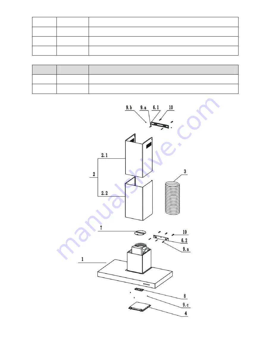
9.a 

5pcs 

Mounting Screws (ST 5 X 50MM) 

9.b 

2pcs 

Chimney Mounting Bracket Screws (M 4 X 10 MM) 

9.c 

3pcs 

Chimney Bottom Fixing Screws (ST 4 X10 MM) 

10 

5pcs 

Drywall Anchors 


Ref 

Q’ty 

Documentations 

14 

1pc 

Instruction Manual 

15 

1pc 

Warranty Card 


Summary of Contents for AKR600IX

Page 1: ...T BOX DECORATIVE COOKER HOOD AKR600IX AKR900IX INSTRUCTION MANUAL ...

Page 2: ...t for many years to come CONTENTS RECOMMENDATIONS AND SUGGESTIONS CHARACTERISTICS INSTALLATION USE MAINTENANCE Product Specification Technical Parameters Model AKR600IX AKR900IX Rated Voltage 220 240V Rated Power Frequency 50Hz Light Power 2x20W 12V Motor Power 250W Total Power 290W Motor 1 Diameter of Exhaust Pipe 150mm Dimension mm L 596 896 x W 500 x H 570 1020 ...

Page 3: ...lers fireplaces etc If the hood is used in conjunction with non electrical appliances e g gas burning appliances a sufficient degree of ventilation must be guaranteed in the room in order to prevent the backflow of exhaust gas The kitchen must have an opening directly with the open air in order to guarantee the entry of clean air The minimum distance is 750mm from the cooker hood to a gas hob and ...

Page 4: ...t disconnect the appliance with wet hands Avoid free flame as it is damaging for the filters and a fire hazard Constantly check food frying to avoid that the overheated oil may become a fire hazard Disconnect the electrical plug prior to any maintenance Children don t recognize the risks of electrical appliances Therefore use or keep the appliance only under supervision of adults and out of the re...

Page 5: ...with controls lights blower filters air outlet adapter 2 1set Telescopic Chimney comprising 2 1 1pc Decorative Chimney Top 2 2 1pc Decorative Chimney Bottom 3 1pc Aluminum Exhaust Duct source locally not supplied 4 1pc Charcoal filter accessory 5 1pc Wall or Roof Cap source locally not supplied Ref Q ty Installation Components 6 1 1pc Chimney Mounting Bracket 6 2 1pc Hood Mounting Bracket 7 1set D...

Page 6: ...ng Screws ST 5 X 50MM 9 b 2pcs Chimney Mounting Bracket Screws M 4 X 10 MM 9 c 3pcs Chimney Bottom Fixing Screws ST 4 X10 MM 10 5pcs Drywall Anchors Ref Q ty Documentations 14 1pc Instruction Manual 15 1pc Warranty Card ...

Page 7: ...e of chimney mounting brackets 6 1 on the wall as shown min 20mm from the ceiling or upper limit aligning the centre notch with the vertical reference line 4 Mark the wall at the centre of the holes in the bracket 5 Place the hood mounting bracket 6 2 on the wall as shown aligning the central notches to the vertical reference line 6 Mark the wall at the centre of the holes in the bracket 7 Drill 1...

Page 8: ...re use metal ductwork is preferred 1 Decide where the ductwork will run between the hood and the outside 2 A straight short duct run will allow the hood to perform most efficiently 3 Long duct runs elbows and transitions will reduce the performance of the hood Use as few of them as possible Larger ducting may be required for best performance with longer duct runs 4 Attach an adequate length of 150...

Page 9: ...ons in order to avoid a hazard Do not use the plug and an extension cord other than the ones initially supplied with the hood The earthing of this hood is compulsory Do not remove ground prong of the plug TELESCOPIC CHIMNEY COMPRISING ASSEMBLY Decorative Chimney Top Raise the decorative chimney top 2 1 up inside the decorative chimney bottom 2 2 Secure decorative chimney top 2 1 to the chimney mou...

Page 10: ... the hood Tilt the filter downward and remove 2 Wash the filters taking care not to bend them Allow them to be dry before refitting 3 When refitting the filters make sure that the handle is visible from the outside 4 To install the grease filter align rear filter tabs with slots in the hood Pull out the latch push filter into position and release Make sure the filter is securely engaged after asse...

Page 11: ...T ROTATE 3 Replace with Type JCD 12V 20W Max G 4 Base halogen bulb Do not touch replacement bulb with bare hands CAUTION 1 THE SURFACE THE COVER OF THE HALOGEN BULBS MAY BE HOT TAKE CARE WHEN TAKING THE REPLACEMENT 2 BULBS MAY BE HOT TAKE CARE WHEN TAKING THE REPLACEMENT OIL CUP 1 To install the oil cup and lock it on to the motor blower 2 The oil cup should be cleaned frequently The oil accumulat...

Page 12: ...c scouring pad or soft bristle brush together with cleanser and water Rub lightly in direction of polishing lines or grain of the stainless finish Avoid using too much pressure that may mar the surface Do not allow deposits to remain for long periods of time Do not use ordinary steel wool or steel brushes Small bits of steel may adhere to the surface causing rust Do not allow salt solutions disinf...

Page 13: ...or The switch is damaged Repair or replace the switch The lamp doesn t work The lamp is damaged Replace the damaged lamp The hood body gives out strong vibrations and a loud noise 1 The hood has not been installed properly according to the installation process described in the instruction manual 2 Check if the joint connection of each part has any damages Ensure the hood has been installed properl...

Page 14: ...Y CARD At the purchase of the appliance properly fill out the product warranty card and properly keep it after having it signed and stamped by the dealer in order to use it in case of need of maintenance service ...

Reviews: