


11
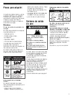
F.
Check operation
4" clamp
4" clamp
Using a 4-inch clamp, connect exhaust
vent to exhaust outlet in dryer. If
connecting to existing exhaust vent,
make sure the vent is clean.
The dryer exhaust vent must fit over
the dryer exhaust outlet and inside the
exhaust hood.
Make sure exhaust vent is secured to
exhaust hood with a 4-inch clamp.
Move dryer into final position. Do not
crush or kink exhaust vent. Make sure
dryer is level.
Check that you:
✔
did not skip any steps.
✔
installed all parts.
✔
properly installed dryer legs.
✔
leveled dryer.
✔
have secured all exhaust vent joints
with 4" clamps.
✔
have all the tools you started with.
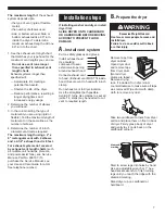
Plug power supply cord into grounded
outlet or connect direct wire to power
supply. Turn power supply on.
Read the Use and Care Guide to fully
understand your new dryer. Select a
full heat cycle (not the air cycle) and
start dryer. After five minutes, open
dryer door. You should feel heat inside
dryer.
If dryer does not operate properly,
check the following:
✔
electrical supply is connected.
✔
house fuse is intact and tight; or
circuit breaker has not tripped.
✔
dryer door is closed.
✔
controls are set in a running or “On”
position.
✔
start button has been pushed firmly.
If dryer makes an unusual noise,
check that dryer is level.
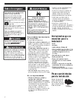
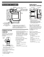
D.
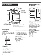
Level and exhaust
dryer
Dryer must be level to reduce noise
and assure proper performance.
Slide dryer onto cardboard or
hardboard before moving across
floor to prevent floor damage.
Move dryer close to its permanent
location. Leave enough room to
connect exhaust vent. Remove
cardboard or hardboard from under
dryer
Check levelness of dryer by placing a
level on top of dryer, first side to side,
then front to back. If dryer is not level,
adjust dryer legs up or down.
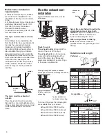
If legs are not long enough to level
dryer, order Extended Dryer Feet Kit,
Part No. 279810 (sold two legs per
kit), from your dealer.
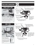
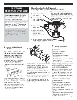
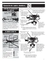
6.
Connect the other
wires to outer terminal
block screws. Tighten
screws.
7.
Tighten strain
relief screws.
8.
Insert tab of terminal
block cover into slot of
dryer rear panel.
Secure cover with hold-
down screw.
5.
Remove the appliance ground wire (green
with yellow stripes) from the external ground
connector screw. Connect appliance ground
wire and the neutral wire (white or center) of
the power supply cord/cable under the
center, silver-colored terminal block screw.
Tighten screw.
9.
Connect a separate copper ground wire
from the external ground connector screw
to an adequate ground.
4.
Remove center terminal
block screw.
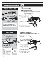
DIRECT WIRE
OR POWER SUPPLY CORD
Where local codes Do Not permit
connecting cabinet-ground conductor to neutral wire:
Three-wire power supply cord must be
four feet long and have three, No.-10
copper wires and match a three-wire
receptacle of NEMA Type 10-30R.
Direct wire power supply cable must be
prepared as shown in “Preparing the wire”
of the three-wire connection direct-wire
steps above.
If codes permit and a separate ground
wire is used, it is recommended that a
qualified electrician determine that the
ground path is adequate.


